|
|
|
PDF IRF6612 Data sheet ( Hoja de datos )
| Número de pieza | IRF6612 | |
| Descripción | HEXFET Power MOSFET | |
| Fabricantes | International Rectifier | |
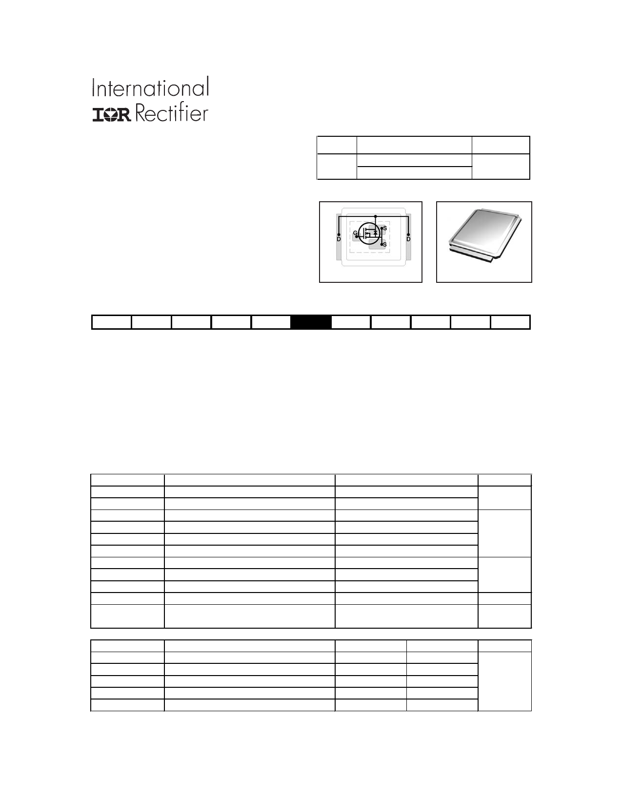
| Logotipo | ||
Hay una vista previa y un enlace de descarga de IRF6612 (archivo pdf) en la parte inferior de esta página. Total 10 Páginas | ||
|
No Preview Available !
PD - 95842
IRF6612/IRF6612TR1
HEXFET® Power MOSFET
l Application Specific MOSFETs
l Ideal for CPU Core DC-DC Converters
l Low Conduction Losses
l Low Switching Losses
l Low Profile (<0.7 mm)
l Dual Sided Cooling Compatible
l Compatible with existing Surface Mount
Techniques
VDSS
30V
RDS(on) max Qg(typ.)
3.3mΩ@VGS = 10V
4.4mΩ@VGS = 4.5V
30nC
MX
DirectFET ISOMETRIC
Applicable DirectFET Package/Layout Pad (see p.8,9 for details)
SQ SX ST
MQ MX MT
Description
The IRF6612 combines the latest HEXFET® Power MOSFET Silicon technology with the advanced DirectFETTM packaging to achieve the
lowest on-state resistance in a package that has the footprint of a SO-8 and only 0.7 mm profile. The DirectFET package is compatible with
existing layout geometries used in power applications, PCB assembly equipment and vapor phase, infra-red or convection soldering tech-
niques, when application note AN-1035 is followed regarding the manufacturing methods and processes. The DirectFET package allows
dual sided cooling to maximize thermal transfer in power systems, IMPROVING previous best thermal resistance by 80%.
The IRF6612 balances both low resistance and low charge along with ultra low package inductance to reduce both conduction and switch-
ing losses. The reduced total losses make this product ideal for high efficiency DC-DC converters that power the latest generation of
processors operating at higher frequencies. The IRF6612 has been optimized for parameters that are critical in synchronous buck convert-
ers including Rds(on), gate charge and Cdv/dt-induced turn on immunity to minimize losses in the synchronous FET socket.
Absolute Maximum Ratings
Parameter
VDS Drain-to-Source Voltage
VGS
ID @ TC = 25°C
ID @ TA = 25°C
ID @ TA = 70°C
IDM
PD @TA = 25°C
PD @TA = 70°C
PD @TC = 25°C
Gate-to-Source Voltage
Continuous Drain Current, VGS @ 10V
Continuous Drain Current, VGS @ 10V
cContinuous Drain Current, VGS @ 10V
Pulsed Drain Current
gPower Dissipation
gPower Dissipation
Power Dissipation
Linear Derating Factor
TJ Operating Junction and
TSTG
Storage Temperature Range
Thermal Resistance
RθJA
RθJA
RθJA
RθJC
RθJ-PCB
Parameter
fjJunction-to-Ambient
gjJunction-to-Ambient
hjJunction-to-Ambient
ijJunction-to-Case
Junction-to-PCB Mounted
Notes through are on page 10
www.irf.com
Max.
30
±20
136
24
19
190
2.8
1.8
89
0.022
-40 to + 150
Typ.
–––
12.5
20
–––
1.0
Max.
45
–––
–––
1.4
–––
Units
V
A
W
W/°C
°C
Units
°C/W
1
02/02/04
1 page 
IRF6612/IRF6612TR1
140
120
100
80
60
40
20
0
25
50 75 100 125
TC , Case Temperature (°C)
150
2.5
2.0
ID = 250µA
1.5
1.0
0.5
0.0
-75 -50 -25 0 25 50 75 100 125 150
TJ , Temperature ( °C )
Fig 9. Maximum Drain Current vs.
Case Temperature
Fig 10. Threshold Voltage vs. Temperature
100
D = 0.50
10 0.20
0.10
0.05
1 0.02
0.01
0.1
0.01
SINGLE PULSE
( THERMAL RESPONSE )
0.001
1E-006
1E-005
0.0001
0.001
τJ τJ
τ1 τ1
R1R1
Ci= τi/Ri
Ci i/Ri
R2R2
τ2 τ2
R3R3
R4R4
τCτ
Ri (°C/W)
1.2801
8.7256
τi (sec)
0.000322
0.164798
τ3 τ3
τ4 τ4
21.750 2.25760
13.251 69
Notes:
1. Duty Factor D = t1/t2
2. Peak Tj = P dm x Zthja + Tc
0.01
0.1
1
10 100
t1 , Rectangular Pulse Duration (sec)
Fig 11. Maximum Effective Transient Thermal Impedance, Junction-to-Ambient
www.irf.com
5
5 Page | ||
| Páginas | Total 10 Páginas | |
| PDF Descargar | [ Datasheet IRF6612.PDF ] | |
Hoja de datos destacado
| Número de pieza | Descripción | Fabricantes |
| IRF6610 | HEXFET Power MOSFET Silicon Technology | International Rectifier |
| IRF6611 | DirectFET Power MOSFET | International Rectifier |
| IRF6611PbF | DirectFET Power MOSFET | International Rectifier |
| IRF6611TRPbF | DirectFET Power MOSFET | International Rectifier |
| Número de pieza | Descripción | Fabricantes |
| SLA6805M | High Voltage 3 phase Motor Driver IC. |
Sanken |
| SDC1742 | 12- and 14-Bit Hybrid Synchro / Resolver-to-Digital Converters. |
Analog Devices |
|
DataSheet.es es una pagina web que funciona como un repositorio de manuales o hoja de datos de muchos de los productos más populares, |
| DataSheet.es | 2020 | Privacy Policy | Contacto | Buscar |