|
|
|
PDF IRF232 Data sheet ( Hoja de datos )
| Número de pieza | IRF232 | |
| Descripción | 8.0A and 9.0A/ 150V and 200V/ 0.4 and 0.6 Ohm/ N-Channel Power MOSFETs | |
| Fabricantes | Intersil Corporation | |
| Logotipo | ||
Hay una vista previa y un enlace de descarga de IRF232 (archivo pdf) en la parte inferior de esta página. Total 7 Páginas | ||
|
No Preview Available !
Semiconductor
October 1997
IRF230, IRF231,
IRF232, IRF233
8.0A and 9.0A, 150V and 200V, 0.4 and 0.6 Ohm,
N-Channel Power MOSFETs
Features
• 8.0A and 9.0A, 150V and 200V
• rDS(ON) = 0.4Ω and 0.6Ω
• Single Pulse Avalanche Energy Rated
• SOA is Power Dissipation Limited
• Nanosecond Switching Speeds
• Linear Transfer Characteristics
• High Input Impedance
• Related Literature
- TB334 “Guidelines for Soldering Surface Mount
Components to PC Boards”
Ordering Information
PART NUMBER
PACKAGE
BRAND
IRF230
TO-204AA
IRF230
IRF231
TO-204AA
IRF231
IRF232
TO-204AA
IRF232
IRF233
TO-204AA
IRF233
NOTE: When ordering, use the entire part number.
Description
These are N-Channel enhancement mode silicon gate
power field effect transistors. They are advanced power
MOSFETs designed, tested, and guaranteed to withstand a
specified level of energy in the breakdown avalanche mode
of operation. All of these power MOSFETs are designed for
applications such as switching regulators, switching conver-
tors, motor drivers, relay drivers, and drivers for high power
bipolar switching transistors requiring high speed and low
gate drive power. These types can be operated directly from
integrated circuits.
Formerly developmental type TA17412.
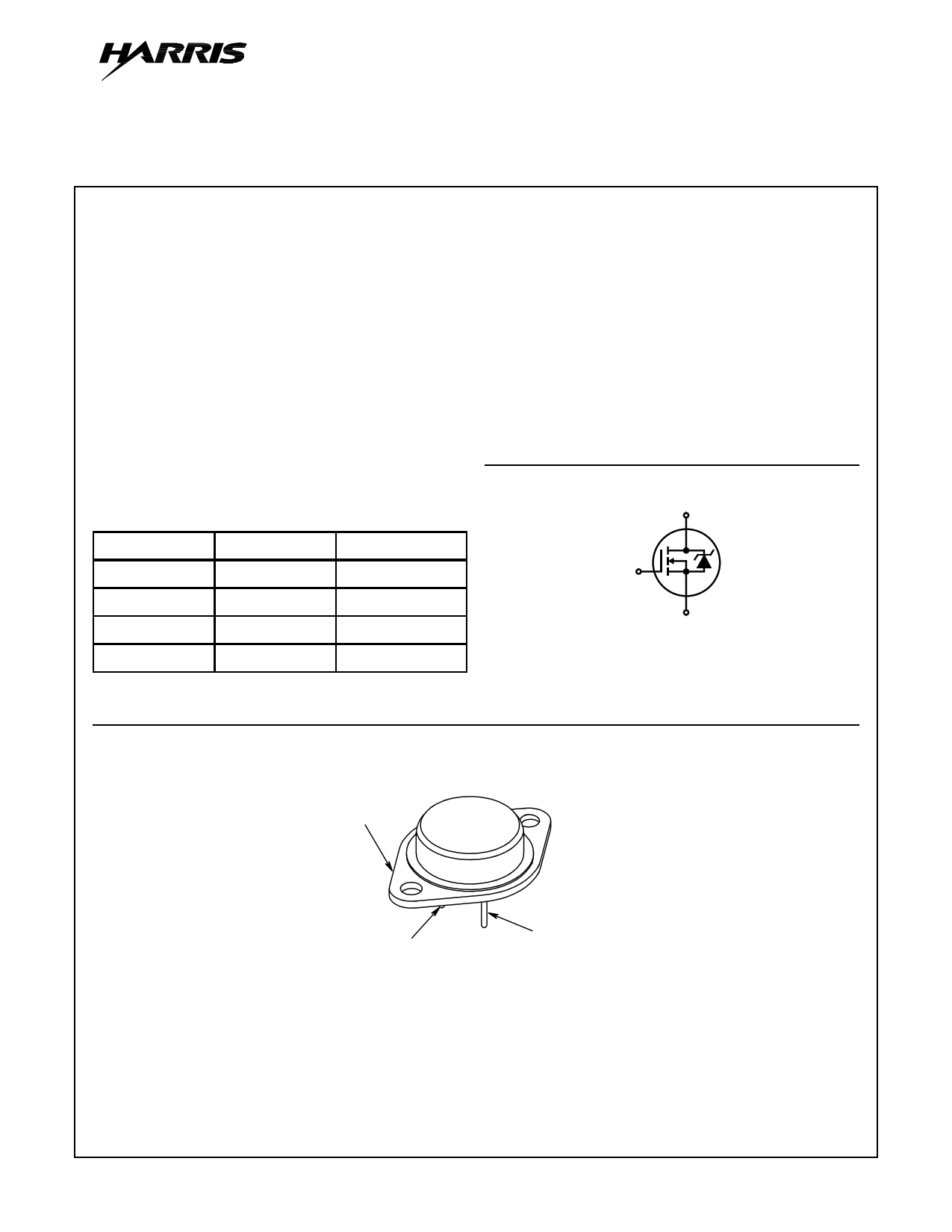
Symbol
D
G
S
Packaging
DRAIN
(FLANGE)
JEDEC TO-204AA
GATE (PIN 1)
SOURCE (PIN 2)
CAUTION: These devices are sensitive to electrostatic discharge. Users should follow proper ESD Handling Procedures.
Copyright © Harris Corporation 1997
1
File Number 1568.2
1 page 
IRF230, IRF231, IRF232, IRF233
Typical Performance Curves Unless Otherwise Specified (Continued)
10
80µs PULSE TEST
8
6
4
10V
9V
8V
7V
6V
VGS = 5.0V
2
4.0V
0
012 34
VDS, DRAIN TO SOURCE VOLTAGE (V)
FIGURE 6. SATURATION CHARACTERISTICS
5
10
VDS > ID(ON) x rDS(ON)MAX
80µs PULSE TEST
8
6
125oC
4 25oC
-55oC
2
0
0123456
VGS, GATE TO SOURCE VOLTAGE (V)
FIGURE 7. TRANSFER CHARACTERISTICS
7
0.8
80µs PULSE TEST
VGS = 10V
0.6
2.2
ID = 3.5A
VGS = 10V
1.8
1.4
1.0
VGS = 20V
0.2
0.6
0
0 10 20 30 40
ID, DRAIN CURRENT (A)
NOTE: Heating effect of 2µs pulse is minimal.
FIGURE 8. DRAIN TO SOURCE ON RESISTANCE vs GATE
VOLTAGE AND DRAIN CURRENT
0.2
-60 -40 -20 0 20 40 60 80 100 120 140
TJ, JUNCTION TEMPERATURE (oC)
FIGURE 9. NORMALIZED DRAIN TO SOURCE ON
RESISTANCE vs JUNCTION TEMPERATURE
1.25
ID = 250µA
1.15
1.05
2000
1600
1200
VGS = 0V, f = 1MHz
CISS = CGS + CGD
CRSS = CGD
COSS ≈ CDS + CGD
0.95
800 CISS
0.85
0.75
-40
0 40 80 120
TJ, JUNCTION TEMPERATURE (oC)
160
FIGURE 10. NORMALIZED DRAIN TO SOURCE BREAKDOWN
VOLTAGE vs JUNCTION TEMPERATURE
400
0
1
COSS
CRSS
10 20 30 40
VDS, DRAIN TO SOURCE VOLTAGE (V)
50
FIGURE 11. CAPACITANCE vs DRAIN TO SOURCE VOLTAGE
5
5 Page | ||
| Páginas | Total 7 Páginas | |
| PDF Descargar | [ Datasheet IRF232.PDF ] | |
Hoja de datos destacado
| Número de pieza | Descripción | Fabricantes |
| IRF230 | N-CHANNEL POWER MOSFETS | Samsung semiconductor |
| IRF230 | N-CHANNEL ENHANCEMENT MODE HIGH VOLTAGE POWER MOSFET | Seme LAB |
| IRF230 | 8.0A and 9.0A/ 150V and 200V/ 0.4 and 0.6 Ohm/ N-Channel Power MOSFETs | Intersil Corporation |
| IRF230 | N-Channel Power MOSFETs/ 12A/ 150-200 V | Fairchild Semiconductor |
| Número de pieza | Descripción | Fabricantes |
| SLA6805M | High Voltage 3 phase Motor Driver IC. |
Sanken |
| SDC1742 | 12- and 14-Bit Hybrid Synchro / Resolver-to-Digital Converters. |
Analog Devices |
|
DataSheet.es es una pagina web que funciona como un repositorio de manuales o hoja de datos de muchos de los productos más populares, |
| DataSheet.es | 2020 | Privacy Policy | Contacto | Buscar |