|
|
|
PDF SG3644Y Data sheet ( Hoja de datos )
| Número de pieza | SG3644Y | |
| Descripción | DUAL HIGH SPEED DRIVER | |
| Fabricantes | Microsemi Corporation | |
| Logotipo | ||
Hay una vista previa y un enlace de descarga de SG3644Y (archivo pdf) en la parte inferior de esta página. Total 8 Páginas | ||
|
No Preview Available !
SG1644/SG2644/SG3644
DUAL HIGH SPEED DRIVER
DESCRIPTION
The SG1644, 2644, 3644 is a dual non-inverting monolithic high
speed driver. This device utilizes high voltage Schottky logic to
convert TTL signals to high speed outputs up to 18V. The totem
pole outputs have 3A peak current capability, which enables them
to drive 1000pF loads in typically less than 25ns. These speeds
make it ideal for driving power MOSFETs and other large capaci-
tive loads requiring high speed switching.
In addition to the standard packages, Silicon General offers the 16
pin S.O.I.C. (DW-package) for commercial and industrial applica-
tions, and the Hermetic TO-66 (R-package) for military use.
These packages offer improved thermal performance for applica-
tions requiring high frequencies and/or high peak currents.
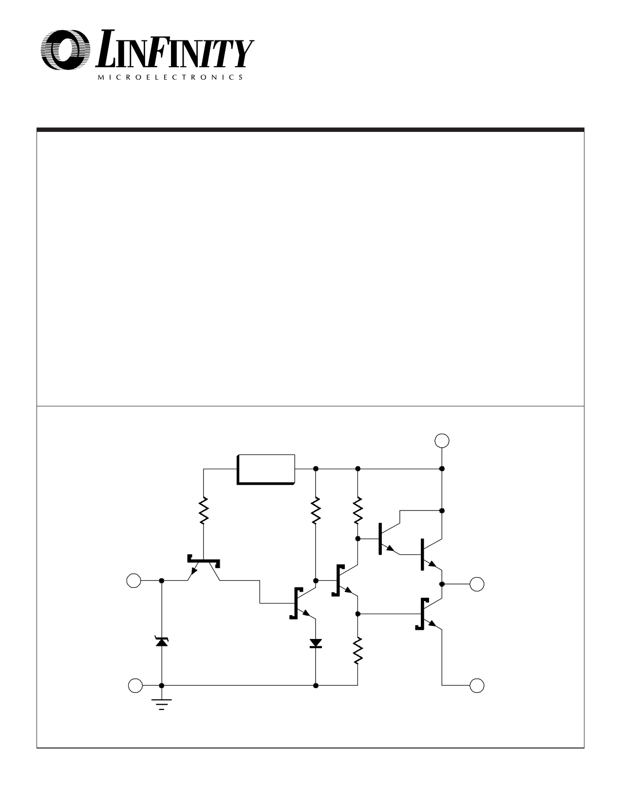
EQUIVALENT CIRCUIT SCHEMATIC
FEATURES
• Totem pole outputs with 3.0A peak current
capability.
• Supply voltage to 22V.
• Rise and fall times less than 25ns.
• Propagation delays less than 20ns.
• Non-inverting high-speed high-voltage Schottky
logic.
• Efficient operation at high frequency.
• Available in:
8 Pin Plastic and Ceramic DIP
14 Pin Ceramic DIP
16 Pin Plastic S.O.I.C.
20 Pin LCC
TO-99
TO-66
HIGH RELIABILITY FEATURES - SG1644
♦ Available to MIL-STD-883
♦ Radiation data available
♦ LMI level "S" processing available
VCC
6.5V
VREG
2.5K
3K 3K
INV. INPUT
OUTPUT
LOGIC
GND
(Substrate)
9/91 Rev 1.2 6/97
Copyright © 1997
POWER
GND
LINFINITY Microelectronics Inc.
11861 Western Avenue ∞ Garden Grove, CA 92841
1 (714) 898-8121 ∞ FAX: (714) 893-2570
1 page 
SG1644/SG2644/SG3644
APPLICATION INFORMATION
POWER DISSIPATION
The SG1644, while more energy-efficient than earlier gold-doped
driver IC’s, can still dissipate considerable power because of its
high peak current capability at high frequencies. Total power
dissipation in any specific application will be the sum of the DC or
steady-state power dissipation, and the AC dissipation caused by
driving capacitive loads.
The DC power dissipation is given by:
PDC = +VCC · ICC [1]
where ICC is a function of the driver state, and hence is duty-cycle
dependent.
The AC power dissipation is proportional to the switching fre-
quency, the load capacitance, and the square of the output
voltage. In most applications, the driver is constantly changing
state, and the AC contribution becomes dominant when the
frequency exceeds 100-200KHz.
The SG1644 driver family is available in a variety of packages to
accommodate a wide range of operating temperatures and power
dissipation requirements. The Absolute Maximums section of the
data sheet includes two graphs to aid the designer in choosing an
appropriate package for his design.
The designer should first determine the actual power dissipation
of the driver by referring to the curves in the data sheet relating
operating current to supply voltage, switching frequency, and
capacitive load. These curves were generated from data taken on
actual devices. The designer can then refer to the Absolute
Maximum Thermal Dissipation curves to choose a package type,
and to determine if heat-sinking is required.
DESIGN EXAMPLE
Given: Two 2500pF loads must be driven push-pull from a +15 volt
supply at 100KHz. The application is a commercial one in which
the maximum ambient temperature is +50°C, and cost is impor-
tant.
1. From Figure 11, the average driver current consumption
under these conditions will be 18mA, and the power dissipation
will be 15volts x 18mA, or 270mW.
2. From the ambient thermal characteristic curve, it can be seen
that the M package, which is an 8-pin plastic DIP with a copper
lead frame, has more than enough thermal conductance from
junction to ambient to support operation at an ambient tempera-
ture of +50°C. The SG36446M driver would be specified for this
application.
SUPPLY BYPASSING
Since the SG1644 can deliver peak currents above 3amps under
some load conditions, adequate supply bypassing is essential for
proper operation. Two capacitors in parallel are recommended to
guarantee low supply impedance over a wide bandwidth: a 0.1µF
ceramic disk capacitor for high frequencies, and a 4.7µF solid
tantalum capacitor for energy storage. In military applications, a
CK05 or CK06 ceramic operator with a CSR-13 tantalum capaci-
tor is an effective combination. For commercial applications, any
low-inductance ceramic disk capacitor teamed with a Sprague
150D or equivalent low ESR capacitor will work well. The
capacitors must be located as close as physically possible to the
VCC pin, with combined lead and pc board trace lengths held to
less than 0.5 inches.
GROUNDING CONSIDERATIONS
The ability of the SG1644 to deliver high peak currents into
capacitive loads can cause undesirable negative transients on
the logic and power grounds. To avoid this, a low inductance
ground path should be considered for each output to return the
high peak currents back to it’s own ground point. A ground plane
is recommended for best performance. If space for a ground
plane is not available, make the paths as short and as wide as
possible. The logic ground can be returned to the supply bypass
capacitor and be connected at one point to the power grounds.
LOGIC INTERFACE
The logic input of the 1644 is designed to accept standard DC-
coupled 5 volt logic swings, with no speed-up capacitors required.
If the input signal voltage exceeds 6 volts, the input pin must be
protected against the excessive voltage in the HIGH state. Either
a high speed blocking diode must be used, or a resistive divider
to attenuate the logic swing is necessary.
LAYOUT FOR HIGH SPEED
The SG1644 can generate relatively large voltage excursions
with rise and fall times around 20-30 nanoseconds with light
capacitive loads. A Fourier analysis of these time domain signals
will indicate strong energy components at frequencies much
higher than the basic switching frequency. These high frequen-
cies can induce ringing on an otherwise ideal pulse if sufficient
inductance occurs in the signal path (either the positive signal
trace or the ground return). Overshoot on the rising edge is
undesirable because the excess drive voltage could rupture
the gate oxide of a power MOSFET. Trailing edge undershoot is
dangerous because the negative voltage excursion can forward-
bias the parasitic PN substrate diode of the driver, potentially
causing erratic operation or outright failure.
Ringing can be reduced or eliminated by minimizing signal path
inductance, and by using a damping resistor between the drive
output and the capacitive load. Inductance can be reduced by
keeping trace lengths short, trace widths wide, and by using 2oz.
copper if possible. The resistor value for critical damping can be
calculated from:
RD = 2√L/CL [2]
where L is the total signal line inductance, and CL is the load
capacitance. Values between 10 and 100ohms are usually
sufficient. Inexpensive carbon composition resistors are best
because they have excellent high frequency characteristics.
They should be located as close as possible to the gate terminal
of the power MOSFET.
9/91 Rev 1.2 6/97
Copyright © 1997
LINFINITY Microelectronics Inc.
11861 Western Avenue ∞ Garden Grove, CA 92841
5 (714) 898-8121 ∞ FAX: (714) 893-2570
5 Page | ||
| Páginas | Total 8 Páginas | |
| PDF Descargar | [ Datasheet SG3644Y.PDF ] | |
Hoja de datos destacado
| Número de pieza | Descripción | Fabricantes |
| SG3644 | DUAL HIGH SPEED DRIVER | Microsemi Corporation |
| SG3644DW | DUAL HIGH SPEED DRIVER | Microsemi Corporation |
| SG3644J | DUAL HIGH SPEED DRIVER | Microsemi Corporation |
| SG3644M | DUAL HIGH SPEED DRIVER | Microsemi Corporation |
| Número de pieza | Descripción | Fabricantes |
| SLA6805M | High Voltage 3 phase Motor Driver IC. |
Sanken |
| SDC1742 | 12- and 14-Bit Hybrid Synchro / Resolver-to-Digital Converters. |
Analog Devices |
|
DataSheet.es es una pagina web que funciona como un repositorio de manuales o hoja de datos de muchos de los productos más populares, |
| DataSheet.es | 2020 | Privacy Policy | Contacto | Buscar |