|
|
|
PDF SL2410N Data sheet ( Hoja de datos )
| Número de pieza | SL2410N | |
| Descripción | Tone Ringer | |
| Fabricantes | System Logic Semiconductor | |
| Logotipo | ||
Hay una vista previa y un enlace de descarga de SL2410N (archivo pdf) en la parte inferior de esta página. Total 6 Páginas | ||
|
No Preview Available !
SL2410
Tone Ringer
The SL2410 is a bipolar integrated circuit designed for telephone bell
replacement.
• Designed for Telephone Bell Replacement
• Low Curent Drain
• Adjustable 2-frequency Tone
• Adjustable Warbling Rate
• Extension Tone Ringer Modules
• Alarms or Other Alerting Devices
• External Triggering or Ringer Disable
• Built-in hysteresis prevents false triggering and rotary dial ‘Chirps’
ORDERING INFORMATION
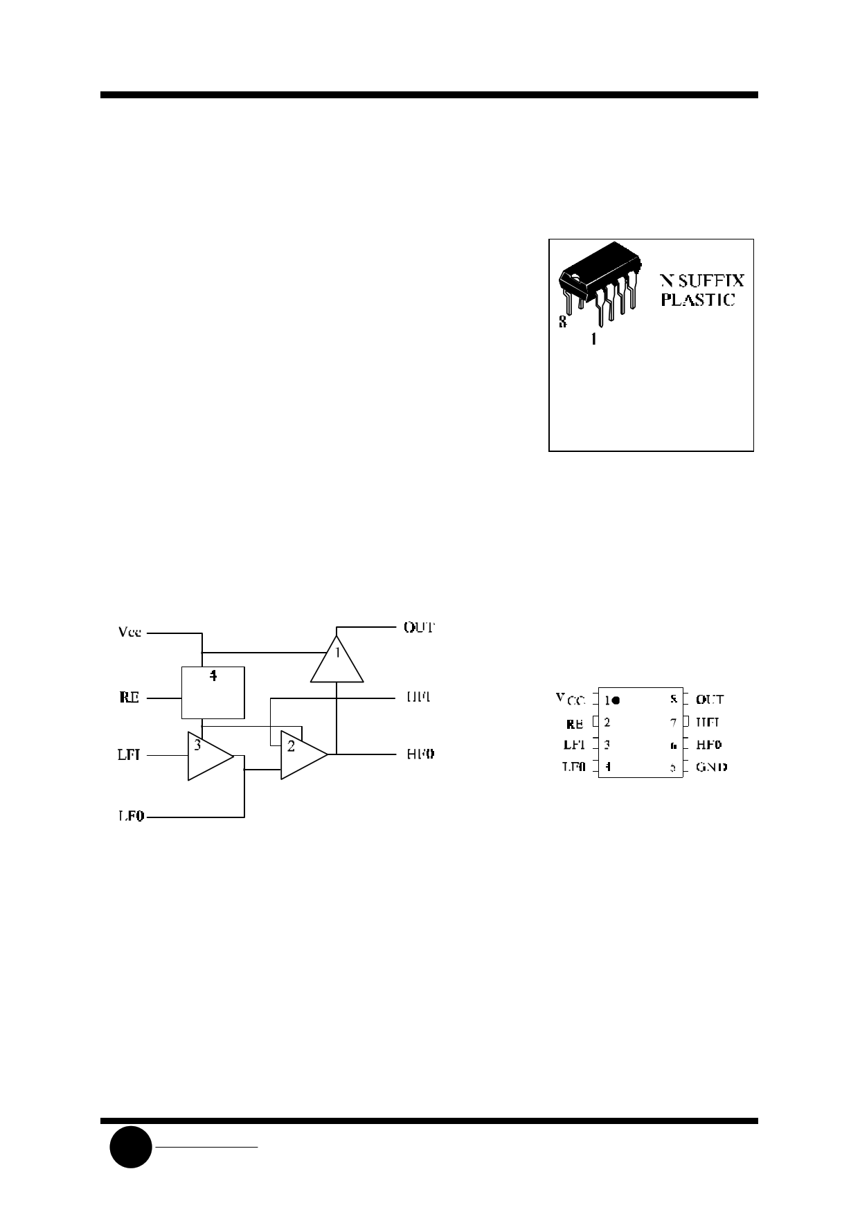
SL2410N Plastic
SL2410D SOIC
TA = -45° to 65° C
for package
LOGIC DIAGRAM
PIN ASSIGNMENT
PIN 1 = VCC
PIN 5 = GND
1. Output amplifier
2. High frequency oscillator
3. Low frequency oscillator
4. Hysteresis regulator
(Regulator circuit has built-in hysteresis to prevent false
triggering and rotary dial “Chirps”)
SLS
System Logic
Semiconductor
1 page 
SL2410
APPLICATION NOTE
The application circuit illustrates the use of the SL2410 devices in typical telephone or extension tone ringer
application.
The AC ringer signal voltage appears across the TIP and RING inputs of the circuit and is attenuated by
capacitor C1 and resistor R1.
C1 also provides isolation from DC voltages (48V) on the exchange line.
After full wave rectification by the bridge diode, the waveform is filtered by capacitor C4 to provide a DC supply
for the tone ringer chip.
As this voltage exceeds the initiation voltage (VSI), oscillation starts.
With the components shown, the ouptut frequency chops between 512(fh1) and 640Hz(fh2) at a 10Hz(fL) rate.
The loudspeaker load is coupled through a 1300Ω to 8Ω ransformer.
The output coupling capacitor C5 is required with transformer coupled loads.
When driving a piezo-ceramic transducer type load, the coupling C5 and transformer (1300Ω:8Ω) are not required.
However, a current limiting resistor is required.
The low frequency oscillator oscillates at a rate (fL) controlled by an external resistor (R2) and capacitor (C2).
The frequency can be determined using the relation fL=1/1.289R2xC2. The high frequency oscillates at a fH1, fH2
controlled by an external resistor (R3) and capacitor (C3). The frequency can be determined using the relation
fH1=1/1.504R3xC3, fH2=1/1.203R3xC3.
TRIGGERING SL2410 FROM CMOS OR TTL LOGIC
Figure 3
Figure 4
SLS
System Logic
Semiconductor
5 Page | ||
| Páginas | Total 6 Páginas | |
| PDF Descargar | [ Datasheet SL2410N.PDF ] | |
Hoja de datos destacado
| Número de pieza | Descripción | Fabricantes |
| SL2410 | Tone Ringer | System Logic Semiconductor |
| SL2410N | Tone Ringer | System Logic Semiconductor |
| Número de pieza | Descripción | Fabricantes |
| SLA6805M | High Voltage 3 phase Motor Driver IC. |
Sanken |
| SDC1742 | 12- and 14-Bit Hybrid Synchro / Resolver-to-Digital Converters. |
Analog Devices |
|
DataSheet.es es una pagina web que funciona como un repositorio de manuales o hoja de datos de muchos de los productos más populares, |
| DataSheet.es | 2020 | Privacy Policy | Contacto | Buscar |