|
|
|
PDF IXGH17N100AU1 Data sheet ( Hoja de datos )
| Número de pieza | IXGH17N100AU1 | |
| Descripción | Low VCE(sat) IGBT with Diode High speed IGBT with Diode | |
| Fabricantes | IXYS Corporation | |
| Logotipo | ||
Hay una vista previa y un enlace de descarga de IXGH17N100AU1 (archivo pdf) en la parte inferior de esta página. Total 6 Páginas | ||
|
No Preview Available !
Low VCE(sat) IGBT with Diode
High speed IGBT with Diode
Combi Packs
IXGH 17 N100U1
IXGH 17 N100AU1
VCES
1000 V
1000 V
IC25
34 A
34 A
VCE(sat)
3.5 V
4.0 V
Symbol
Test Conditions
Maximum Ratings TO-247 AD
VCES
VCGR
VGES
VGEM
IC25
IC90
ICM
SSOA
(RBSOA)
TJ = 25°C to 150°C
TJ = 25°C to 150°C; RGE = 1 MΩ
Continuous
Transient
TC = 25°C
TC = 90°C
TC = 25°C, 1 ms
VGE= 15 V, TVJ = 125°C, RG = 82 Ω
Clamped inductive load, L = 100 µH
PC
TJ
TJM
Tstg
Md
Weight
TC = 25°C
Mounting torque (M3)
Maximum lead temperature for soldering
1.6 mm (0.062 in.) from case for 10 s
1000
1000
V
V
±20 V
±30 V
34 A
17 A
68 A
ICM = 34
@ 0.8 V
CES
150
A
W
-55 ... +150
150
-55 ... +150
°C
°C
°C
1.13/10 Nm/lb.in.
6g
300 °C
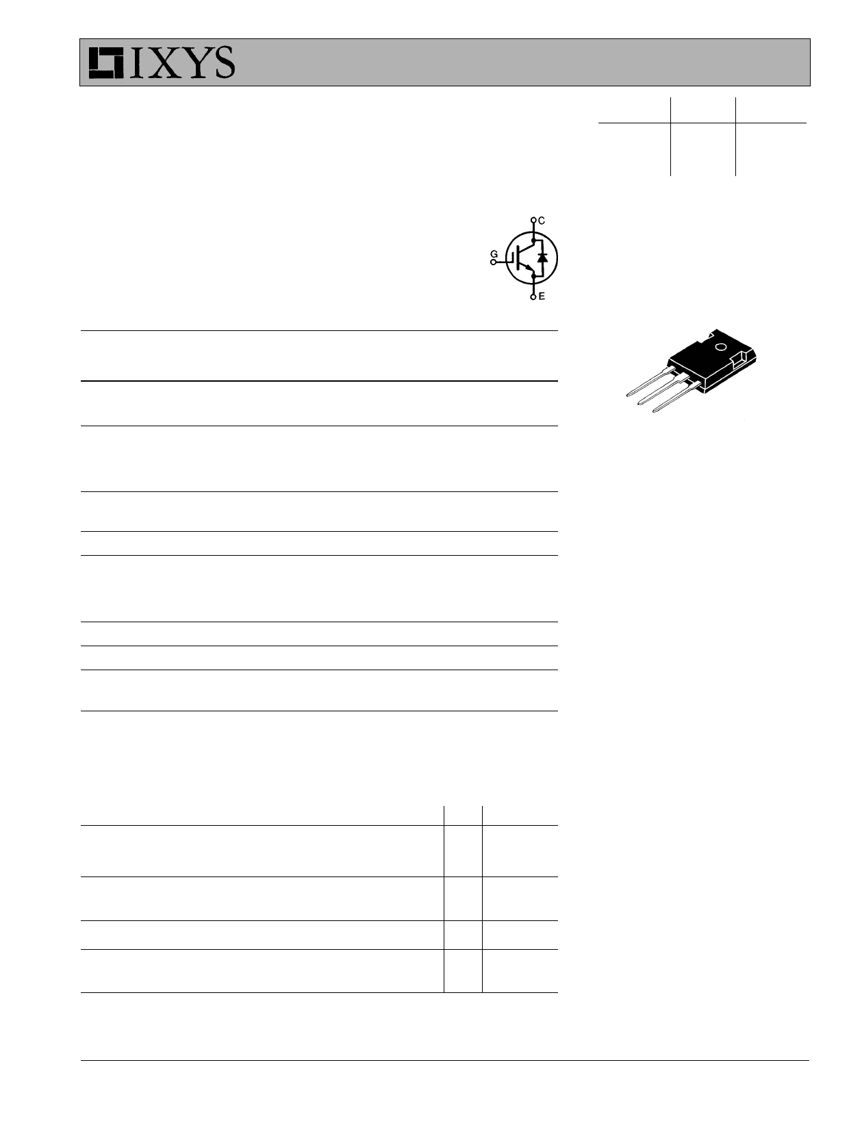
G
C
E
G = Gate,
E = Emitter,
C = Collector,
TAB = Collector
Features
l International standard package
JEDEC TO-247 AD
l IGBT and anti-parallel FRED in one
package
l 2nd generation HDMOSTM process
l Low V
CE(sat)
- for minimum on-state conduction
losses
l MOS Gate turn-on
- drive simplicity
l Fast Recovery Epitaxial Diode (FRED)
- soft recovery with low I
RM
Symbol
BVCES
V
GE(th)
I
CES
IGES
VCE(sat)
Test Conditions
Characteristic Values
(TJ = 25°C, unless otherwise specified)
min. typ. max.
IC = 4.5 mA, VGE = 0 V
I
C
=
500
µA,
V
CE
=
V
GE
V = 0.8 • V
CE CES
VGE = 0 V
VCE = 0 V, VGE = ±20 V
IC = IC90, VGE = 15 V
T
J
=
25°C
TJ = 125°C
1000
2.5
17N100U1
17N100AU1
V
5.5 V
500 µA
8 mA
±100 nA
3.5 V
4.0 V
Applications
l AC motor speed control
l DC servo and robot drives
l DC choppers
l Uninterruptible power supplies (UPS)
l Switch-mode and resonant-mode
power supplies
Advantages
l Saves space (two devices in one
package)
l Easy to mount (isolated mounting
screw hole)
l Reduces assembly time and cost
© 1996 IXYS All rights reserved
91754D (3/96)
1 page 
IXGH 17N100U1
IXGH 17N100AU1
Fig.11 Maximum Forward Voltage Drop
100
80
60
40
20
0
0.5
TJ = 100°C
TJ = 150°C
TJ = 25°C
1.0 1.5 2.0 2.5 3.0
Voltage Drop - Volts
3.5
Fig.13 Junction Temperature Dependence
off IRM and Qr
1.4
1.2
1.0
0.8
IRM
0.6
0.4 Qr
0.2
0.0
0
40 80 120 160
TJ - Degrees C
Fig.15 Peak Reverse Recovery Current
50
TJ = 100°C
VR = 540V
40
max.
IF = 30A
30
20
typ.
IF = 60A
10 IF = 30A
IF = 15A
0
200 400 600
diF /dt - A/µs
© 1996 IXYS All rights reserved
Fig.12 Peak Forward Voltage VFR and
Forward Recovery Time tFR
50
TJ = 125°C
IF =37A
40
1000
VFR
800
30 600
20 400
tfr
10 200
00
0 100 200 300 400 500 600
diF /dt - A/µs
Fig.14 Reverse Recovery Chargee
4
TJ = 100°C
VR = 540V
3
2
1
typ.
IF = 60A
IF = 30A
IF = 15A
max.
IF = 30A
0
1 10 100 1000
diF /dt - A/µs
Fig.16 Reverse Recovery Time
0.8
max.
IF = 30A
0.6
0.4
0.2
TJ = 100°C
VR = 540V
typ.
IF = 60A
IF = 30A
IF = 15A
0.0
0
200 400
diF /dt - A/µs
600
5 Page | ||
| Páginas | Total 6 Páginas | |
| PDF Descargar | [ Datasheet IXGH17N100AU1.PDF ] | |
Hoja de datos destacado
| Número de pieza | Descripción | Fabricantes |
| IXGH17N100AU1 | Low VCE(sat) IGBT with Diode High speed IGBT with Diode | IXYS Corporation |
| Número de pieza | Descripción | Fabricantes |
| SLA6805M | High Voltage 3 phase Motor Driver IC. |
Sanken |
| SDC1742 | 12- and 14-Bit Hybrid Synchro / Resolver-to-Digital Converters. |
Analog Devices |
|
DataSheet.es es una pagina web que funciona como un repositorio de manuales o hoja de datos de muchos de los productos más populares, |
| DataSheet.es | 2020 | Privacy Policy | Contacto | Buscar |