|
|
|
PDF HV857 Data sheet ( Hoja de datos )
| Número de pieza | HV857 | |
| Descripción | High Voltage EL Lamp Driver IC | |
| Fabricantes | Supertex Inc | |
| Logotipo | ||
Hay una vista previa y un enlace de descarga de HV857 (archivo pdf) en la parte inferior de esta página. Total 9 Páginas | ||
|
No Preview Available !
Supertex inc.
HV857
Low Noise, High Voltage
EL Lamp Driver IC
Features
►►Patented audible noise reduction
►►Patented lamp aging compensation
►►190 VPP output voltage for higher brightness
►►Patented output timing for high efficiency
►►Single cell lithium ion compatible
►►150nA shutdown current
►►Wide input voltage range 1.8 to 5.0V
►►Separately adjustable lamp and converter
frequencies
►►Output voltage regulation
►►Split supply capability
►►Available in 8-Lead MSOP and DFN packages
Applications
►► LCD backlighting
►► Mobile Cellular Phone
►► PDAs
►► Handheld wireless communication products
►► Global Positioning Systems (GPS)
General Description
The Supertex HV857 is a high voltage driver designed for driving
Electroluminescent (EL) lamps of up to 5.0 square inches. The
input supply voltage range is from 1.8 to 5.0V. The device uses
a single inductor and a minimum number of passive components.
The nominal regulated output voltage that is applied to the EL
lamp is ±95V. The chip can be enabled/disabled by connecting the
resistor on RSW-Osc to VDD/GND.
The HV857 has two internal oscillators, a switching MOSFET, and
a high voltage EL lamp driver. The frequency for the switching
MOSFET is set by an external resistor connected between
the RSW-Osc pin and the supply pin VDD. The EL lamp driver
frequency is set by an external resistor connected between REL-
Osc pin and VDD pin. An external inductor is connected between
the LX and VDD pins or VIN for split supply applications. A 0.003-
0.1µF capacitor is connected between CS and ground. The EL
lamp is connected between VA and VB.
The switching MOSFET charges the external inductor and
discharges it into the capacitor at CS. The voltage at CS will start
to increase. Once the voltage at CS reaches a nominal value of
95V, the switching MOSFET is turned OFF to conserve power. The
outputs VA and VB are configured as an H bridge and are switching
in opposite states to achieve ±95V across the EL lamp.
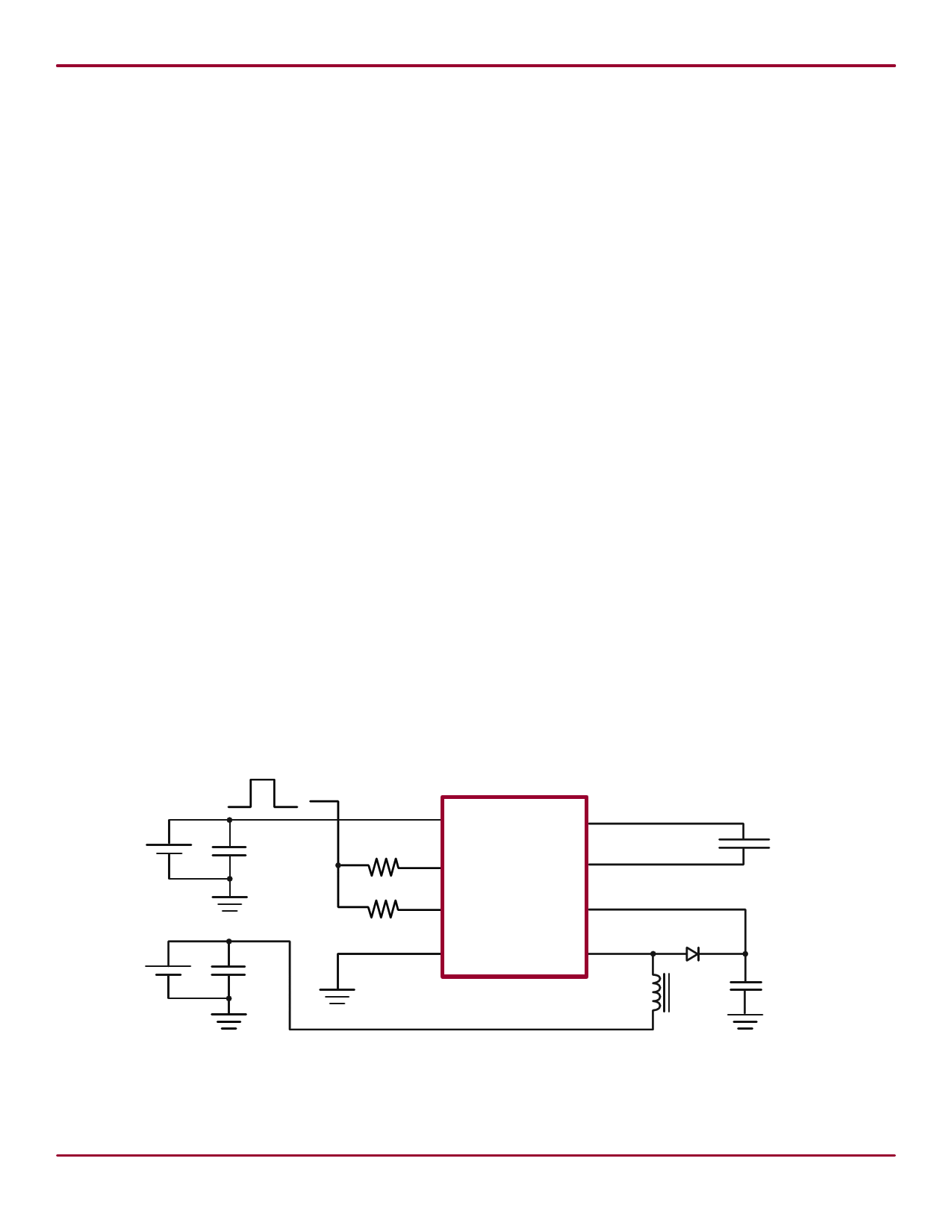
Typical Application Circuit
ON = VDD
Enable Signal
OFF = 0
+
_VDD
CDD
1 VDD
VA 8
RSW
HV857
2 RSW-Osc
VB 7
EL Lamp
+
_VIN
3 REL-Osc
CS 6
REL
4 GND
LX 5
D
CIN LX CS
Doc.# DSFP-HV857
A062013
Supertex inc.
www.supertex.com
1 page 
External Component Description
External
Component
Description
Diode
Fast reverse recovery diode, BAS21 diode or equivalent.
HV857
CS Capacitor
0.003µF to 0.1µF, 100V capacitor to GND is used to store the energy transferred from the inductor.
The EL lamp frequency is controlled via an external REL resistor connected between REL-Osc and VDD
of the device. The lamp frequency increases as REL decreases. As the EL lamp frequency increases,
the amount of current drawn from the battery will increase and the output voltage VCS will decrease. The
color of the EL lamp is dependent upon its frequency.
REL Resistor
A 2MΩ resistor would provide lamp frequency of 205 to 275Hz. Decreasing the REL resistor by a factor
of 2 will increase the lamp frequency by a factor of 2.
fEL
=
(2MΩ)(240Hz)
REL
RSW Resistor
The switching frequency of the converter is controlled via an external resistor, RSW between RSW-Osc
and VDD of the device. The switching frequency increases as RSW decreases. With a given inductor, as
the switching frequency increases, the amount of current drawn from the battery will decrease and the
output voltage, VCS, will also decrease.
fSW
=
(560kΩ)(80Hz)
RSW
LX Inductor
Lamp
The inductor LX is used to boost the low input voltage by inductive flyback. When the internal switch is
on, the inductor is being charged. When the internal switch is off, the charge stored in the inductor will
be transferred to the high voltage capacitor CS. The energy stored in the capacitor is connected to the
internal H-bridge, and therefore to the EL lamp. In general, smaller value inductors, which can handle
more current, are more suitable to drive larger size lamps. As the inductor value decreases, the switch-
ing frequency of the inductor (controlled by RSW) should be increased to avoid saturation.
A 220µH Murata (LQH32CN221) inductor with 8.4Ω series DC resistance is typically recommended. For
inductors with the same inductance value, but with lower series DC resistance, lower RSW resistor value
is needed to prevent high current draw and inductor saturation.
As the EL lamp size increases, more current will be drawn from the battery to maintain high voltage
across the EL lamp. The input power, (VIN x IIN), will also increase. If the input power is greater than
the power dissipation of the package, an external resistor in series with one side of the lamp is recom-
mended to help reduce the package power dissipation.
Doc.# DSFP-HV857
A062013
Supertex inc.
5 www.supertex.com
5 Page | ||
| Páginas | Total 9 Páginas | |
| PDF Descargar | [ Datasheet HV857.PDF ] | |
Hoja de datos destacado
| Número de pieza | Descripción | Fabricantes |
| HV850 | Inductorless EL Lamp Driver | Supertex |
| HV852 | Inductorless EL Lamp Driver | Supertex |
| HV853 | Inductorless EL Lamp Driver | Supertex |
| HV857 | High Voltage EL Lamp Driver IC | Supertex Inc |
| Número de pieza | Descripción | Fabricantes |
| SLA6805M | High Voltage 3 phase Motor Driver IC. |
Sanken |
| SDC1742 | 12- and 14-Bit Hybrid Synchro / Resolver-to-Digital Converters. |
Analog Devices |
|
DataSheet.es es una pagina web que funciona como un repositorio de manuales o hoja de datos de muchos de los productos más populares, |
| DataSheet.es | 2020 | Privacy Policy | Contacto | Buscar |