|
|
|
PDF HUF76407D3S Data sheet ( Hoja de datos )
| Número de pieza | HUF76407D3S | |
| Descripción | 11A/ 60V/ 0.107 Ohm/ N-Channel/ Logic Level UltraFET Power MOSFET | |
| Fabricantes | Fairchild Semiconductor | |
| Logotipo | ||
Hay una vista previa y un enlace de descarga de HUF76407D3S (archivo pdf) en la parte inferior de esta página. Total 10 Páginas | ||
|
No Preview Available !
Data Sheet
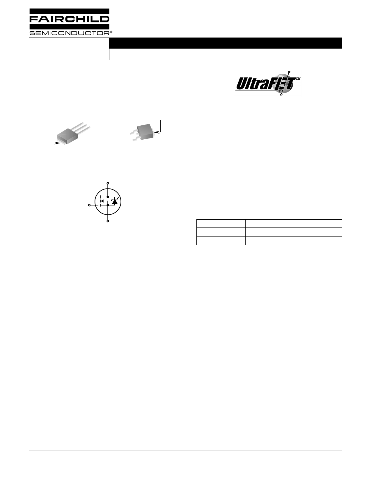
HUF76407D3, HUF76407D3S
December 2001
11A, 60V, 0.107 Ohm, N-Channel, Logic
Level UltraFET® Power MOSFET
Packaging
JEDEC TO-251AA
DRAIN
(FLANGE)
SOURCE
DRAIN
GATE
HUF76407D3
JEDEC TO-252AA
DRAIN
(FLANGE)
GATE
SOURCE
HUF76407D3S
Symbol
D
G
S
Features
• Ultra Low On-Resistance
- rDS(ON) = 0.092Ω, VGS = 10V
- rDS(ON) = 0.107Ω, VGS = 5V
• Simulation Models
- Temperature Compensated PSPICE® and SABER™
Electrical Models
- Spice and SABER Thermal Impedance Models
- www.fairchildsemi.com
• Peak Current vs Pulse Width Curve
• UIS Rating Curve
• Switching Time vs RGS Curves
Ordering Information
PART NUMBER
PACKAGE
BRAND
HUF76407D3
TO-251AA
76407D
HUF76407D3S
TO-252AA
76407D
NOTE: When ordering, use the entire part number. Add the suffix T to
obtain the TO-252AA variant in tape and reel, e.g., HUF76407D3ST.
Absolute Maximum Ratings TC = 25oC, Unless Otherwise Specified
HUF76407D3,
HUF76407D3S
UNITS
Drain to Source Voltage (Note 1) . . . . . . . . . . . . . . . . . . . . . . . . . . . . . . . . . . . . . . . . . . . . . . . VDSS
Drain to Gate Voltage (RGS = 20kΩ) (Note 1) . . . . . . . . . . . . . . . . . . . . . . . . . . . . . . . . . . . . . VDGR
Gate to Source Voltage . . . . . . . . . . . . . . . . . . . . . . . . . . . . . . . . . . . . . . . . . . . . . . . . . . . . . . . VGS
Drain Current
Continuous (TC = 25oC, VGS = 5V) . . . . . . . . . . . . . . . . . . . . . . . . . . . . . . . . . . . . . . . . . . . . . . ID
Continuous
Continuous
Continuous
(TC
(TC
(TC
=
=
=
21153355oCooCC, V,, VVGGGSSS===1054VV.5))V(.)F.(i.gF.uig.rue.r.2e.)2.)..
.
.
.
.
.
.
.
.
.
.
.
.
.
.
.
.
.
.
.
.
.
.
.
.
.
.
.
.
.
.
.
.
.
.
.
.
.
.
.
.
.
.
.
.
.
.
.
.
.
.
.
.
.
.
.
.
.
.
.
.
.
.
.
.
.
.
.
.
.
.
.
.
.
.
.
.
.
.
.
.
.
.
.
.
.
.
.
.
.
.
.
.
.
.
.
.
.
.
.
.
.
.
.
.
.
ID
ID
ID
Pulsed Drain Current . . . . . . . . . . . . . . . . . . . . . . . . . . . . . . . . . . . . . . . . . . . . . . . . . . . . . . . .IDM
Pulsed Avalanche Rating . . . . . . . . . . . . . . . . . . . . . . . . . . . . . . . . . . . . . . . . . . . . . . . . . . . . . .UIS
60
60
±16
11
12
6
6
Figure 4
Figures 6, 14, 15
V
V
V
A
A
A
A
Power Dissipation . . .
Derate Above 25oC
.
.
.
.
.
.
.
.
.
.
.
.
.
.
.
.
.
.
.
.
.
.
.
.
.
.
.
.
.
.
.
.
.
.
.
.
.
.
.
.
.
.
.
.
.
.
.
.
.
.
.
.
.
.
.
.
.
.
.
.
.
.
.
.
.
.
.
.
.
.
.
.
.
.
.
.
.
.
.
.
.
.
.
.
.
.
.
.
.
.
.
.
.
.
.
.
.
.
.
.
.
.
.
.
.
.
.
.
.
.
.
.
.
.
PD
...
Operating and Storage Temperature . . . . . . . . . . . . . . . . . . . . . . . . . . . . . . . . . . . . . . . . . TJ, TSTG
Maximum Temperature for Soldering
Leads at 0.063in (1.6mm) from Case for 10s. . . . . . . . . . . . . . . . . . . . . . . . . . . . . . . . . . . . . . .TL
Package Body for 10s, See Techbrief TB334 . . . . . . . . . . . . . . . . . . . . . . . . . . . . . . . . . . . . . Tpkg
NOTE:
38
0.25
-55 to 175
300
260
W
W/oC
oC
oC
oC
1. TJ = 25oC to 150oC.
CAUTION: Stresses above those listed in “Absolute Maximum Ratings” may cause permanent damage to the device. This is a stress only rating and operation of the
device at these or any other conditions above those indicated in the operational sections of this specification is not implied.
For severe environments, see our Automotive HUFA series.
©2001 Fairchild Semiconductor Corporation
HUF76407D3, HUF76407D3S Rev. B
1 page 
HUF76407D3, HUF76407D3S
Typical Performance Curves (Continued)
1.2 1.2
VGS = VDS, ID = 250µA
ID = 250µA
1.0 1.1
0.8 1.0
0.6
-80 -40
0
40 80 120 160 200
TJ, JUNCTION TEMPERATURE (oC)
FIGURE 11. NORMALIZED GATE THRESHOLD VOLTAGE vs
JUNCTION TEMPERATURE
1000
CISS = CGS + CGD
COSS ≅ CDS + CGD
100
10
0.1
VGS = 0V, f = 1MHz
CRSS = CGD
1.0 10
VDS, DRAIN TO SOURCE VOLTAGE (V)
60
FIGURE 13. CAPACITANCE vs DRAIN TO SOURCE VOLTAGE
150
VGS = 4.5V, VDD = 30V, ID = 6A
100
tr
tf
50
td(OFF)
td(ON)
0
0 10 20 30 40
RGS, GATE TO SOURCE RESISTANCE (Ω)
50
FIGURE 15. SWITCHING TIME vs GATE RESISTANCE
0.9
-80 -40
0
40 80 120 160 200
TJ, JUNCTION TEMPERATURE (oC)
FIGURE 12. NORMALIZED DRAIN TO SOURCE BREAKDOWN
VOLTAGE vs JUNCTION TEMPERATURE
10
VDD = 30V
8
6
4 WAVEFORMS IN
DESCENDING ORDER:
2 ID = 12A
ID = 5A
ID = 3A
0
0 2 4 6 8 10
Qg, GATE CHARGE (nC)
NOTE: Refer to Fairchild Application Notes AN7254 and AN7260.
FIGURE 14. GATE CHARGE WAVEFORMS FOR CONSTANT
GATE CURRENT
80
VGS = 10V, VDD = 30V, ID = 12A
60
40
tf
tr
20
td(OFF)
td(ON)
0
0 10 20 30 40
RGS, GATE TO SOURCE RESISTANCE (Ω)
50
FIGURE 16. SWITCHING TIME vs GATE RESISTANCE
©2001 Fairchild Semiconductor Corporation
HUF76407D3, HUF76407D3S Rev. B
5 Page | ||
| Páginas | Total 10 Páginas | |
| PDF Descargar | [ Datasheet HUF76407D3S.PDF ] | |
Hoja de datos destacado
| Número de pieza | Descripción | Fabricantes |
| HUF76407D3 | 11A/ 60V/ 0.107 Ohm/ N-Channel/ Logic Level UltraFET Power MOSFET | Fairchild Semiconductor |
| HUF76407D3 | 11A/ 60V/ 0.107 Ohm/ N-Channel/ Logic Level UltraFET Power MOSFET | Intersil Corporation |
| HUF76407D3S | 11A/ 60V/ 0.107 Ohm/ N-Channel/ Logic Level UltraFET Power MOSFET | Fairchild Semiconductor |
| HUF76407D3S | 11A/ 60V/ 0.107 Ohm/ N-Channel/ Logic Level UltraFET Power MOSFET | Intersil Corporation |
| Número de pieza | Descripción | Fabricantes |
| SLA6805M | High Voltage 3 phase Motor Driver IC. |
Sanken |
| SDC1742 | 12- and 14-Bit Hybrid Synchro / Resolver-to-Digital Converters. |
Analog Devices |
|
DataSheet.es es una pagina web que funciona como un repositorio de manuales o hoja de datos de muchos de los productos más populares, |
| DataSheet.es | 2020 | Privacy Policy | Contacto | Buscar |