|
|
|
PDF HUF75531SK8 Data sheet ( Hoja de datos )
| Número de pieza | HUF75531SK8 | |
| Descripción | 6A/ 80V/ 0.030 Ohm/ N-Channel/ UltraFET Power MOSFET | |
| Fabricantes | Intersil Corporation | |
| Logotipo | ||
Hay una vista previa y un enlace de descarga de HUF75531SK8 (archivo pdf) en la parte inferior de esta página. Total 12 Páginas | ||
|
No Preview Available !
TM
Data Sheet
6A, 80V, 0.030 Ohm, N-Channel,
UltraFET Power MOSFET
Packaging
JEDEC MS-012AA
BRANDING DASH
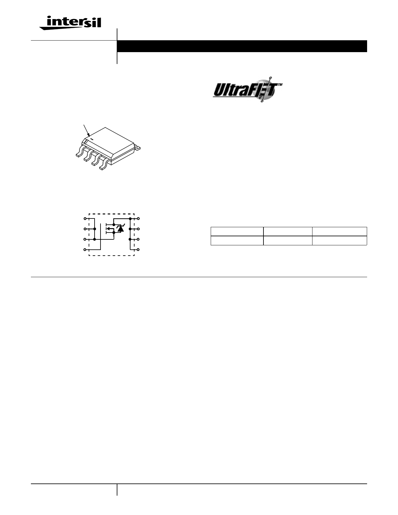
1
2
3
4
5
Symbol
SOURCE (1)
SOURCE (2)
SOURCE (3)
GATE (4)
DRAIN (8)
DRAIN (7)
DRAIN (6)
DRAIN (5)
HUF75531SK8
April 2000
File Number 4848
Features
• Ultra Low On-Resistance
- rDS(ON) = 0.030Ω, VGS = 10V
• Simulation Models
- Temperature Compensated PSPICE™ and SABER©
Electrical Models
- Spice and SABER© Thermal Impedance Models
- www.intersil.com
• Peak Current vs Pulse Width Curve
• UIS Rating Curve
Ordering Information
PART NUMBER
PACKAGE
BRAND
HUF75531SK8
MS-012AA
75531SK8
NOTE: When ordering, use the entire part number. Add the suffix T
to obtain the variant in tape and reel, e.g., HUF75531SK8T.
Absolute Maximum Ratings TA = 25oC, Unless Otherwise Specified
HUF75531SK8
UNITS
Drain to Source Voltage (Note 1) . . . . . . . . . . . . . . . . . . . . . . . . . . . . . . . . . . . . . . . . . . . . . VDSS
Drain to Gate Voltage (RGS = 20kΩ) (Note 1) . . . . . . . . . . . . . . . . . . . . . . . . . . . . . . . . . . .VDGR
Gate to Source Voltage . . . . . . . . . . . . . . . . . . . . . . . . . . . . . . . . . . . . . . . . . . . . . . . . . . . . . VGS
Drain Current
Continuous
Continuous
(TA=
(TA=
2150o0CoC, V, VGGSS==101V0V) )(F(Figiugruere2)2).
.
.
.
.
.
.
.
.
.
.
.
.
.
.
.
.
.
.
.
.
.
.
.
.
.
.
.
.
.
.
.
.
.
.
.
.
.
.
.
.
.
.
.
.
.
.
.
.
.
.
.
.
.
.
.
.
.
.
.
.
.
.
. ID
. ID
Pulsed Drain Current . . . . . . . . . . . . . . . . . . . . . . . . . . . . . . . . . . . . . . . . . . . . . . . . . . . . . IDM
Pulsed Avalanche Rating . . . . . . . . . . . . . . . . . . . . . . . . . . . . . . . . . . . . . . . . . . . . . . . . . . . UIS
80
80
±20
6
4
Figure 4
Figures 6, 14, 15
V
V
V
A
A
Power Dissipation . . .
Derate Above 25oC
.
.
.
.
.
.
.
.
.
.
.
.
.
.
.
.
.
.
.
.
.
.
.
.
.
.
.
.
.
.
.
.
.
.
.
.
.
.
.
.
.
.
.
.
.
.
.
.
.
.
.
.
.
.
.
.
.
.
.
.
.
.
.
.
.
.
.
.
.
.
.
.
.
.
.
.
.
.
.
.
.
.
.
.
.
.
.
.
.
.
.
.
.
.
.
.
.
.
.
.
.
.
.
.
.
.
.
.
.
.
PD
..
Operating and Storage Temperature . . . . . . . . . . . . . . . . . . . . . . . . . . . . . . . . . . . . . . . TJ, TSTG
Maximum Temperature for Soldering
Leads at 0.063in (1.6mm) from Case for 10s. . . . . . . . . . . . . . . . . . . . . . . . . . . . . . . . . . . . TL
Package Body for 10s, See Techbrief TB370 . . . . . . . . . . . . . . . . . . . . . . . . . . . . . . . . . . .Tpkg
NOTES:
1. TJ = 25oC to 125oC.
2. 50oC/W measured using FR-4 board with 0.76 in2 (490.3 mm2) copper pad at 10 second.
3. 152oC/W measured using FR-4 board with 0.054 in2 (34.8 mm2) copper pad at 1000 seconds
4. 189oC/W measured using FR-4 board with 0.0115 in2 (7.42 mm2) copper pad at 1000 seconds
2.5
20
-55 to 150
300
260
W
mW/oC
oC
oC
oC
CAUTION: Stresses above those listed in “Absolute Maximum Ratings” may cause permanent damage to the device. This is a stress only rating and operation of the
device at these or any other conditions above those indicated in the operational sections of this specification is not implied.
1 CAUTION: These devices are sensitive to electrostatic discharge. Follow proper ESD Handling Procedures.
UltraFET™ is a trademark of Intersil Corporation. PSPICE® is a registered trademark of MicroSim Corporation.
1-888-INTERSIL or 321-724-7143 | Intersil and Design is a trademark of Intersil Corporation. | Copyright © Intersil Corporation 2000
1 page 
HUF75531SK8
Typical Performance Curves (Continued)
1.2
ID = 250µA
1.1
1.0
0.9
-80
-40 0 40 80 120
TJ, JUNCTION TEMPERATURE (oC)
160
FIGURE 11. NORMALIZED DRAIN TO SOURCE BREAKDOWN
VOLTAGE vs JUNCTION TEMPERATURE
10
VDD = 40V
8
3000
1000
COSS ≅ CDS + CGD
VGS = 0V, f = 1MHz
CISS = CGS + CGD
100
CRSS = CGD
30
0.1
1.0 10
VDS, DRAIN TO SOURCE VOLTAGE (V)
80
FIGURE 12. CAPACITANCE vs DRAIN TO SOURCE VOLTAGE
6
4
WAVEFORMS IN
DESCENDING ORDER:
2 ID = 6A
ID = 1A
0
0 10 20 30 40
Qg, GATE CHARGE (nC)
NOTE: Refer to Intersil Application Notes AN7254 and AN7260.
FIGURE 13. GATE CHARGE WAVEFORMS FOR CONSTANT GATE CURRENT
Test Circuits and Waveforms
VARY tP TO OBTAIN
REQUIRED PEAK IAS
VGS
tP
0V
RG
VDS
L
DUT
+
VDD
-
IAS
0.01Ω
FIGURE 14. UNCLAMPED ENERGY TEST CIRCUIT
tP
IAS
BVDSS
VDS
VDD
0
tAV
FIGURE 15. UNCLAMPED ENERGY WAVEFORMS
5
5 Page 
HUF75531SK8
MS-012AA
8 LEAD JEDEC MS-012AA SMALL OUTLINE PLASTIC PACKAGE
EA
E1 A1
e
D
b
h x 45o
c
L
0.060
1.52
0o- 8o
0.004 IN
0.10 mm
0.050
1.27
0.155
4.0
0.275
7.0
0.024
0.6
MINIMUM RECOMMENDED FOOTPRINT FOR
SURFACE-MOUNTED APPLICATIONS
1.5mm
DIA. HOLE
MS-012AA
12mm TAPE AND REEL
12mm
INCHES
MILLIMETERS
SYMBOL MIN MAX MIN MAX NOTES
A
0.0532 0.0688 1.35
1.75
-
A1
0.004
0.0098 0.10
0.25
b
0.013
0.020
0.33
0.51
-
-
c
0.0075 0.0098 0.19
0.25
-
D
0.189
0.1968 4.80
5.00
2
E
0.2284 0.244
5.80
6.20
-
E1 0.1497 0.1574 3.80 4.00
e 0.050 BSC
1.27 BSC
3
-
H
0.0099 0.0196 0.25
0.50
-
L
0.016
0.050
0.40
1.27
4
NOTES:
1. All dimensions are within allowable dimensions of Rev. C of
JEDEC MS-012AA outline dated 5-90.
2. Dimension “D” does not include mold flash, protrusions or gate
burrs. Mold flash, protrusions or gate burrs shall not exceed
0.006 inches (0.15mm) per side.
3. Dimension “E1” does not include inter-lead flash or protrusions.
Inter-lead flash and protrusions shall not exceed 0.010 inches
(0.25mm) per side.
4. “L” is the length of terminal for soldering.
5. The chamfer on the body is optional. If it is not present, a visual index
feature must be located within the crosshatched area.
6. Controlling dimension: Millimeter.
7. Revision 8 dated 5-99.
4.0mm
USER DIRECTION OF FEED
2.0mm
1.75mm
CL
COVER TAPE
8.0mm
40mm MIN.
ACCESS HOLE
18.4mm
330mm
13mm
50mm
GENERAL INFORMATION
1. 2500 PIECES PER REEL.
2. ORDER IN MULTIPLES OF FULL REELS ONLY.
3. MEETS EIA-481 REVISION “A” SPECIFICATIONS.
11
12.4mm
11 Page | ||
| Páginas | Total 12 Páginas | |
| PDF Descargar | [ Datasheet HUF75531SK8.PDF ] | |
Hoja de datos destacado
| Número de pieza | Descripción | Fabricantes |
| HUF75531SK8 | 6A/ 80V/ 0.030 Ohm/ N-Channel/ UltraFET Power MOSFET | Fairchild Semiconductor |
| HUF75531SK8 | 6A/ 80V/ 0.030 Ohm/ N-Channel/ UltraFET Power MOSFET | Intersil Corporation |
| Número de pieza | Descripción | Fabricantes |
| SLA6805M | High Voltage 3 phase Motor Driver IC. |
Sanken |
| SDC1742 | 12- and 14-Bit Hybrid Synchro / Resolver-to-Digital Converters. |
Analog Devices |
|
DataSheet.es es una pagina web que funciona como un repositorio de manuales o hoja de datos de muchos de los productos más populares, |
| DataSheet.es | 2020 | Privacy Policy | Contacto | Buscar |