|
|
|
PDF ISL62773 Data sheet ( Hoja de datos )
| Número de pieza | ISL62773 | |
| Descripción | Multiphase PWM Regulator | |
| Fabricantes | Intersil | |
| Logotipo | ||
Hay una vista previa y un enlace de descarga de ISL62773 (archivo pdf) en la parte inferior de esta página. Total 30 Páginas | ||
|
No Preview Available !
DATASHEET
Multiphase PWM Regulator for AMD Fusion™ Desktop
CPUs Using SVI 2.0
ISL62773
The ISL62773 is fully compliant with AMD Fusion™ SVI 2.0 and
provides a complete solution for desktop microprocessor and
graphics processor core power. The ISL62773 controller supports
two Voltage Regulators (VRs) with three integrated gate drivers
and two optional external drivers for maximum flexibility. The
Core VR can be configured for 3-, 2-, or 1-phase operation while
the Northbridge VR supports 2- or 1-phase configurations. The two
VRs share a serial control bus to communicate with the AMD CPU
and achieve lower cost and smaller board area compared with
two-chip solutions.
The PWM modulator is based on Intersil’s Robust Ripple
Regulator R3™ technology. Compared to traditional modulators,
the R3 modulator can automatically change switching frequency
for faster transient settling time during load transients and
improved light-load efficiency.
The ISL62773 has several other key features. Both outputs
support DCR current sensing with a single NTC thermistor for
DCR temperature compensation or accurate resistor current
sensing. Both outputs utilize remote voltage sense, adjustable
switching frequency, OC protection and power-good.
Applications
• AMD Fusion CPU/GPU core power
• Desktop computers
Features
• Supports AMD SVI 2.0 serial data bus interface
- Serial VID clock frequency range 100kHz to 25MHz
• Dual output controller with integrated drivers
- Two dedicated core drivers
- One programmable driver for either core or Northbridge
• Precision voltage regulation
- 0.5% system accuracy over-temperature
- 0.5V to 1.55V in 6.25mV steps
- Enhanced load line accuracy
• Supports multiple current sensing methods
- Lossless inductor DCR current sensing
- Precision resistor current sensing
• Programmable 1-, 2- or 3-phase for the core output and 1- or
2-phase for the Northbridge output
• Adaptive body diode conduction time reduction
• Superior noise immunity and transient response
• Output current monitor and thermal monitor
• Differential remote voltage sensing
• High efficiency across entire load range
• Programmable slew rate, VID offset, droop and switching
frequency on both outputs
• OCP/WOC, OVP, PGOOD and thermal monitor
• Small footprint 48 Ld 6x6 QFN Package
- Pb-free (RoHS compliant)
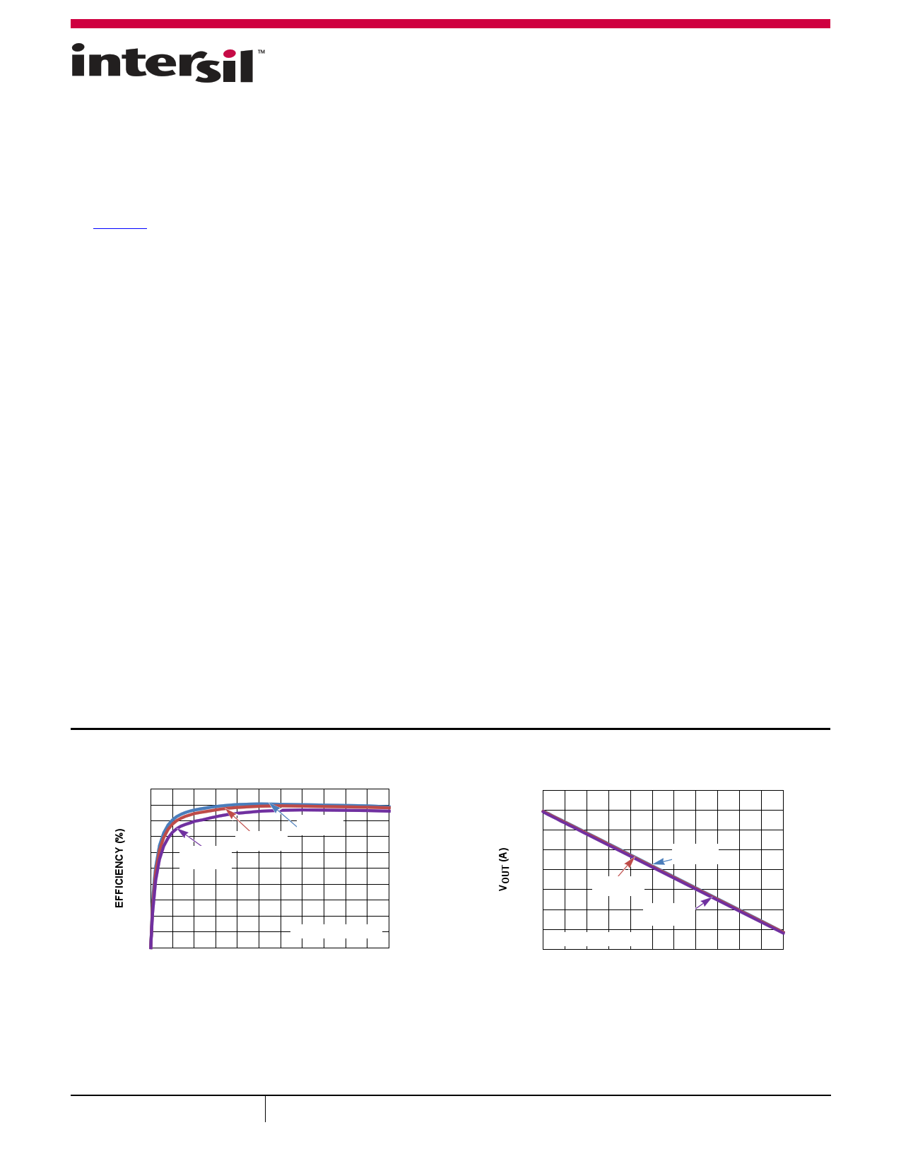
Core Performance
100
90
80
70
60
50
40
30
20
10
0
0
VIN = 12V
VIN = 19V
VIN = 8V
VOUT CORE = 1.1V
5 10 15 20 25 30 35 40 45 50 55
IOUT (A)
FIGURE 1. EFFICIENCY vs LOAD
1.12
1.10
1.08
1.06
1.04
1.02
VIN = 12V
VIN = 8V
1.00
VIN = 19V
0.98 VOUT CORE = 1.1V
0.96 0 5 10 15 20 25 30 35 40 45 50 55
IOUT (A)
FIGURE 2. VOUT vs LOAD
December 16, 2015
FN8263.1
1
CAUTION: These devices are sensitive to electrostatic discharge; follow proper IC Handling Procedures.
1-888-INTERSIL or 1-888-468-3774 | Copyright Intersil Americas LLC 2012, 2015. All Rights Reserved
Intersil (and design) and R3 Technology are trademarks owned by Intersil Corporation or one of its subsidiaries.
All other trademarks mentioned are the property of their respective owners.
1 page 
ISL62773
Simplified Application Circuit for Mid-Power CPUs [2+1 Configuration]
* Resistor required or ISEN1_NB
will pull HIGH if left open and
disable Channel 1.
10kΩ*
NBN
NBP
+5V
Ri
NTC
Cn
ISEN1_NB
ISEN2_NB
ISUMN_NB
ISUMP_NB
PWM_Y
FCCM_NB
PWM2_NB OPEN
VIN
VNB
NBP
NBN
VNB_SENSE
VCORE_SENSE
VP1
VP2
VN1
VN2
µP
+5V
Ri
Cn NTC
COMP_NB
FB_NB
IMON_NB
NTC_NB
VSEN_NB
PWROK
SVT
SVD
SVC
VDDIO
BOOTX
UGATEX
PHASEX
LGATEX
VR_HOT_L
IMON
COMP
ISL62773
NTC
FB2
FB
VSEN
RTN
ISEN1
ISEN2
ISEN3
BOOT2
UGATE2
PHASE2
LGATE2
BOOT1
ISUMN
UGATE1
PHASE1
OPEN
OPEN
OPEN
OPEN
THERMAL INDICATOR
VIN
VP2
VIN
VN2
ISUMP
LGATE1
VP1 VN1
VCORE
FIGURE 5. TYPICAL APPLICATION CIRCUIT USING RESISTOR SENSING
Submit Document Feedback
5
FN8263.1
December 16, 2015
5 Page 
ISL62773
Absolute Maximum Ratings
Supply Voltage, VDD, VDDP . . . . . . . . . . . . . . . . . . . . . . . . . . . . . -0.3V to +7V
Battery Voltage, VIN . . . . . . . . . . . . . . . . . . . . . . . . . . . . . . . . . . . . . . . . . +28V
Boot Voltage (BOOT) . . . . . . . . . . . . . . . . . . . . . . . . . . . . . . . . . . -0.3V to +33V
Boot to Phase Voltage (BOOT-PHASE) . . . . . . . . . . . . . . . . -0.3V to +7V (DC)
. . . . . . . . . . . . . . . . . . . . . . . . . . . . . . . . . . . . . . . . . . .-0.3V to +9V (<10ns)
Phase Voltage (PHASE) . . . . . . . . . . . . . . . . -7V (<20ns Pulse Width, 10µJ)
UGATE Voltage (UGATE) . . . . . . . . . PHA SE - 0.3V (DC) to BOOTPHASE - 5V
. . . . . . . . . . . . . . . . . (<20ns Pulse Width, 10µJ) to BOOT LGATE Voltage
. . . . . . . . . . . . . . . . . . . . . -2.5V (<20ns Pulse Width, 5µJ) to VDD + 0.3V
All Other Pins . . . . . . . . . . . . . . . . . . . . . . . . . . . . . . . . -0.3V to (VDD + 0.3V)
Open-Drain Outputs, PGOOD, PGOOD_NB, VR_HOT_L. . . . . . -0.3V to +7V
Thermal Information
Thermal Resistance (Typical)
JA (°C/W) JC (°C/W)
48 Ld QFN Package (Notes 4, 5) . . . . . . . .
29
3.5
Maximum Junction Temperature . . . . . . . . . . . . . . . . . . . . . . . . . . . .+150°C
Maximum Storage Temperature Range . . . . . . . . . . . . . .-65°C to +150°C
Maximum Junction Temperature (Plastic Package) . . . . . . . . . . . .+150°C
Storage Temperature Range. . . . . . . . . . . . . . . . . . . . . . . .-65°C to +150°C
Pb-free Reflow Profile . . . . . . . . . . . . . . . . . . . . . . . . . . . . . . . . . . see TB493
Recommended Operating Conditions
Supply Voltage, VDD . . . . . . . . . . . . . . . . . . . . . . . . . . . . . . . . . . . . . . +5V ±5%
Battery Voltage, VIN . . . . . . . . . . . . . . . . . . . . . . . . . . . . . . . . . . +4.5V to 25V
Ambient Temperature
HRZ. . . . . . . . . . . . . . . . . . . . . . . . . . . . . . . . . . . . . . . . . . .-10°C to +100°C
IRZ . . . . . . . . . . . . . . . . . . . . . . . . . . . . . . . . . . . . . . . . . . . . -40°C to +85°C
Junction Temperature . . . . . . . . . . . . . . . . . . . . . . . . . . . . .-10°C to +125°C
CAUTION: Do not operate at or near the maximum ratings listed for extended periods of time. Exposure to such conditions may adversely impact product
reliability and result in failures not covered by warranty.
NOTES:
4. JA is measured in free air with the component mounted on a high effective thermal conductivity test board with “direct attach” features. See Tech
Brief TB379.
5. For JC, the “case temp” location is the center of the exposed metal pad on the package underside.
Electrical Specifications Operating Conditions: VDD = 5V, TA = -10°C to +100°C (HRZ), TA = -40°C to +85°C (IRZ), fSW = 300kHz, unless
otherwise noted. Boldface limits apply across the operating temperature range, -40°C to +100°C.
PARAMETER
SYMBOL
TEST CONDITIONS
MIN MAX
(Note 6) TYP (Note 6) UNIT
INPUT POWER SUPPLY
+5V Supply Current
IVDD
ENABLE = 1V
ENABLE = 0V
8 11 mA
5 µA
Battery Supply Current
VIN Input Resistance
POWER-ON-RESET THRESHOLDS
IVIN
RVIN
ENABLE = 0V
ENABLE = 1V
1
620
µA
kΩ
VDD POR Threshold
SYSTEM AND REFERENCES
VDD_PORr
VDD_PORf
VDD rising
VDD falling
4.00
4.35
4.15
4.5
V
V
System Accuracy
HRZ
%Error (VOUT)
No load; closed loop, active mode range,
VID = 0.75V to 1.55V,
VID = 0.25V to 0.74375V
-0.5
-10
+0.5
+10
%
mV
IRZ
%Error (VOUT)
No load; closed loop, active mode range,
VID = 0.75V to 1.55V
VID = 0.25V to 0.74375V
-0.8
-12
+0.8
+12
%
mV
Maximum Output Voltage
Minimum Output Voltage
CHANNEL FREQUENCY
VOUT(max)
VOUT(min)
VID = [00000000]
VID = [11111111]
1.55
0.0
V
V
Nominal Channel Frequency
Adjustment Range
fSW(nom)
280 300 320
300 450
kHz
kHz
Submit Document Feedback 11
FN8263.1
December 16, 2015
11 Page | ||
| Páginas | Total 30 Páginas | |
| PDF Descargar | [ Datasheet ISL62773.PDF ] | |
Hoja de datos destacado
| Número de pieza | Descripción | Fabricantes |
| ISL6277 | Multiphase PWM Regulator | Intersil |
| ISL62771 | Multiphase PWM Regulator | Intersil |
| ISL62773 | Multiphase PWM Regulator | Intersil |
| ISL62773A | Multiphase PWM Regulator | Intersil |
| Número de pieza | Descripción | Fabricantes |
| SLA6805M | High Voltage 3 phase Motor Driver IC. |
Sanken |
| SDC1742 | 12- and 14-Bit Hybrid Synchro / Resolver-to-Digital Converters. |
Analog Devices |
|
DataSheet.es es una pagina web que funciona como un repositorio de manuales o hoja de datos de muchos de los productos más populares, |
| DataSheet.es | 2020 | Privacy Policy | Contacto | Buscar |