|
|
|
PDF IRS21814PbF Data sheet ( Hoja de datos )
| Número de pieza | IRS21814PbF | |
| Descripción | HIGH AND LOW SIDE DRIVER | |
| Fabricantes | International Rectifier | |
| Logotipo | ||
Hay una vista previa y un enlace de descarga de IRS21814PbF (archivo pdf) en la parte inferior de esta página. Total 23 Páginas | ||
|
No Preview Available !
www.DataSheet4U.com
Data Sheet No. PD60262
IRS2181/IRS21814(S)PbF
HIGH AND LOW SIDE DRIVER
Features
• Floating channel designed for bootstrap operation
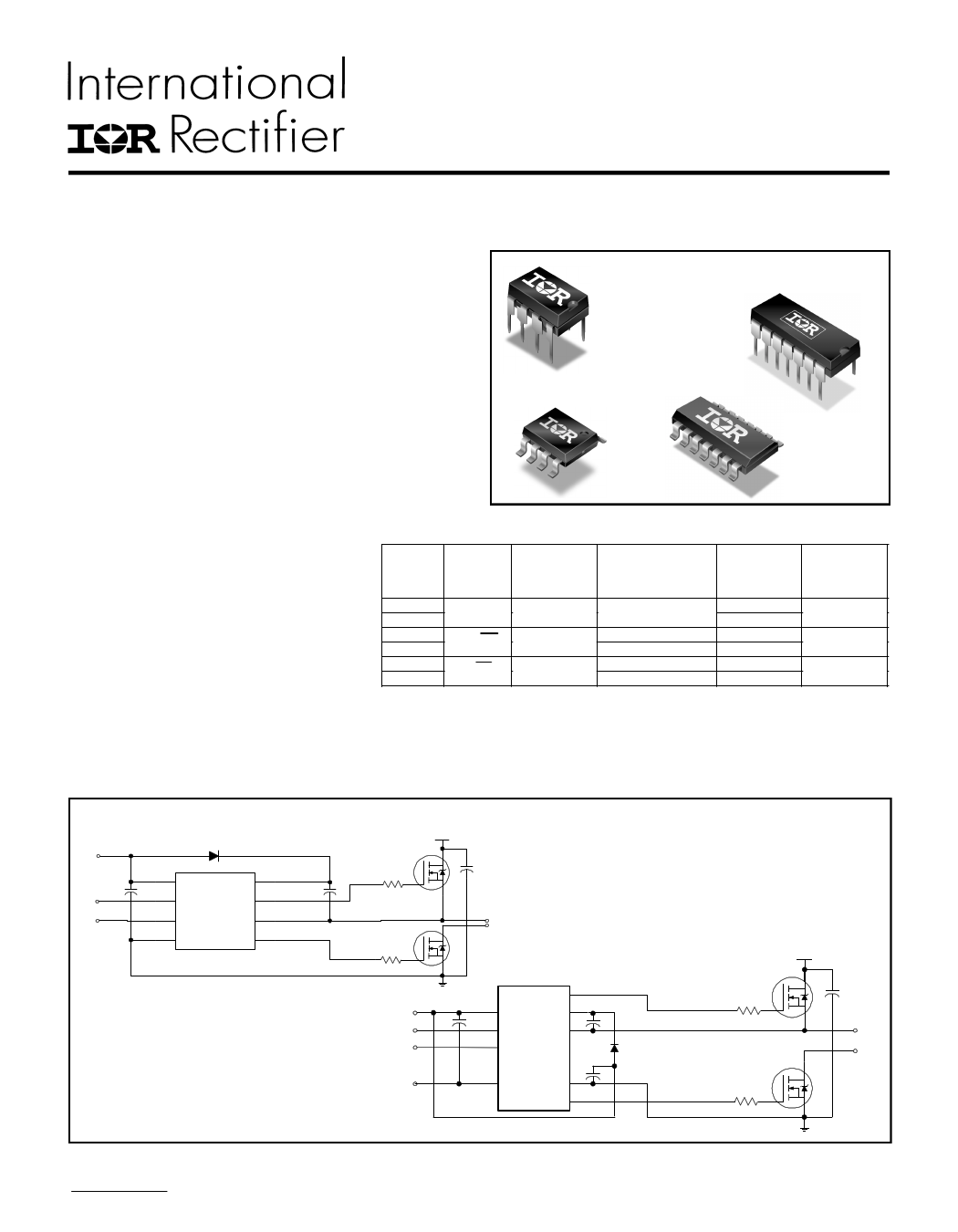
Packages
• Fully operational to +600 V
• Tolerant to negative transient voltage, dV/dt
8-Lead PDIP
IRS2181
14-Lead PDIP
IRS21814
immune
• Gate drive supply range from 10 V to 20 V
• Undervoltage lockout for both channels
• 3.3 V and 5 V input logic compatible
• Matched propagation delay for both channels
8-Lead SOIC
• Logic and power ground +/- 5 V offset
IRS2181S
• Lower di/dt gate driver for better noise immunity
• Output source/sink current capability 1.4 A/1.8 A
• RoHS compliant
14-Lead SOIC
IRS21814S
Description
Feature Comparison
The IRS2181/IRS21814 are high
voltage, high speed power MOSFET
and IGBT drivers with independent
high-side and low-side referenced
output channels. Proprietary HVIC
and latch immune CMOS technolo-
gies enable ruggedized monolithic
construction. The logic input is com-
Part
2181
21814
2183
21834
2184
21844
Input
logic
HIN/LIN
HIN/LIN
IN/SD
Cross-
conduction
prevention
logic
no
yes
yes
Deadtime
(ns)
none
Internal 400
Program 400-5000
Internal 400
Program 400-5000
Ground Pins
COM
VSS/COM
COM
VSS/COM
COM
VSS/COM
ton/toff
(ns)
180/220
180/220
680/270
patible with standard CMOS or LSTTL output, down to 3.3 V logic. The output drivers feature a high pulse
current buffer stage designed for minimum driver cross-conduction. The floating channel can be used to drive
an N-channel power MOSFET or IGBT in the high-side configuration which operates up to 600 V.
Typical Connection
V CC
VCC
VB
HIN HIN HO
LIN LIN VS
COM
LO
IRS2181
(Refer to Lead Assignments for correct pin
configuration). These diagrams show
electrical connections only. Please refer to
our Application Notes and DesignTips for
proper circuit board layout.
up to 600 V
TO
LOAD
HO
VCC
VCC
VB
HIN HIN VS
LIN LIN
VSS VSS COM
LO
IRS21814
up to 600 V
TO
LOAD
www.irf.com
1
1 page 
IRS2181/IRS21814(S)PbF
Lead Definitions
Symbol Description
HIN Logic input for high-side gate driver output (HO), in phase (IRS2181/IRS21814)
LIN Logic input for low-side gate driver output (LO), in phase (IRS2181/IRS21814)
VSS
Logic ground (IRS21814 only)
VB High-side floating supply
HO High-side gate drive output
VS High-side floating supply return
VCC Low-side and logic fixed supply
LO Low-side gate drive output
COM
Low-side return
Lead Assignments
1 HIN
2 LIN
3 COM
4 LO
VB
HO
VS
VCC
8
7
6
5
8-Lead PDIP
IRS2181PbF
1 HIN
14
2 LIN
VB 13
3 VSS
HO 12
4 VS 11
5 COM
10
6 LO
9
7 VCC
8
14-Lead PDIP
IRS21814PbF
www.irf.com
1 HIN
2 LIN
3 COM
4 LO
VB
HO
VS
VCC
8
7
6
5
8-Lead SOIC
IRS2181SPbF
1 HIN
2 LIN
3 VSS
4
5 COM
6 LO
7 VCC
14
VB 13
HO 12
VS 11
10
9
8
14-Lead SOIC
IRS21814SPbF
5
5 Page 
IRS2181/IRS21814(S)PbF
500
400
300
200
100
Max.
0
-50 -25
0 25 50 75 100 125
Temperature (oC)
Figure 12A. Offset Supply Leakage Current
vs. Tem perature
250
200
150
Max.
100
Typ.
50
0
-50 -25
Mi n.
0 25 50 75 100 125
Temperature (oC)
Figure 13A. VBS Supply Current
vs. Tem perature
50 0
400
300
200
100 Max.
0
100 200 300 400 500 600
VB Boost Voltage (V)
Figure 12B. Offset Supply Leakage
Current vs. VB Boost Voltage
250
200
150 Max.
100 Typ.
50 Mi n.
0
10 12 14 16 18
VBS Floating Supply Voltage (V)
Figure 13B. VBS Supply Current
vs. VBS Floating Supply Voltage
20
www.irf.com
11
11 Page | ||
| Páginas | Total 23 Páginas | |
| PDF Descargar | [ Datasheet IRS21814PbF.PDF ] | |
Hoja de datos destacado
| Número de pieza | Descripción | Fabricantes |
| IRS21814PbF | HIGH AND LOW SIDE DRIVER | International Rectifier |
| Número de pieza | Descripción | Fabricantes |
| SLA6805M | High Voltage 3 phase Motor Driver IC. |
Sanken |
| SDC1742 | 12- and 14-Bit Hybrid Synchro / Resolver-to-Digital Converters. |
Analog Devices |
|
DataSheet.es es una pagina web que funciona como un repositorio de manuales o hoja de datos de muchos de los productos más populares, |
| DataSheet.es | 2020 | Privacy Policy | Contacto | Buscar |