No Preview Available !

1-1-3 DC/DC Converter ICs
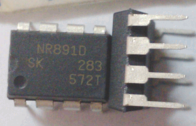
NR887D/NR891D Full-Mold, Separate Excitation Step-down Switching Mode Regulator ICs
■Features
Current Mode Control, Synchronous Rectifier Step-down Switching Mode
■Absolute Maximum Ratings
• DIP 8 pin package
• Input voltage range (VIN): VO + 3 to 18 V
• Synchronous rectifier mode
• High efficiency: 90%
• Introduction of current mode control method
• A ceramic capacitor can be used for output
• Built-in phase correction component
• Output current: 2 A
• Reference voltage and accuracy of 0.8 V ± 2%
• Oscillation frequency: 500 kHz
• Output ON/OFF available
• Undervoltage lockout
• Soft start function
■Applications
Parameter
Input Voltage
Power Dissipation
Junction Temperature
Storage Temperature
Thermal Resistance (Junction to Lead (4 pins))
Thermal Resistance (Junction to Ambient Air)
Symbol
VIN
PD
Tj
Tstg
θj-c
θj-a
Ratings
20
1.50
–40 to +150
–40 to +150
25
67
Unit
V
W
°C
°C
°C/W
°C/W
Conditions
When mounted on a 70 × 60 mm glass-epoxy board (with a 1310 mm2 copper area)
When mounted on a 70 × 60 mm glass-epoxy board (with a 1310 mm2 copper area)
■Recommended Operating Conditions
Parameter
Input Voltage Range
Output Current Range
Output Voltage Range
Operating Temperature Range
Ratings
4.5 or VO + 3* to 18
0 2.0
0.8 to 14
–40 to +85
*: The minimum value of the input voltage range is 4.5 V or VO + 3 V, whichever is higher.
Unit
V
A
V
°C
• Power supply for LCDTV and PDP
• Power supply for DVD, BD, and STB
• On-board local power supply
• Power supply for switches
■Electrical Characteristics
Reference Voltage
Temperature Coefficient of Reference Voltage
Efficiency
Oscillation Frequency
Line Regulation
Load Regulation
Overcurrent Protection Starting Current
Quiescent Circuit Current 1
Quiescent Circuit Current 2
SS Pin
Outflow Current at Low Voltage
Open Voltage
EN Pin
Inflow Current
On Threshold Voltage
Maximum ON Duty
Minimum ON Time
Thermal Protection Start Temperature
Thermal Protection Return Hysteresis
η
min.
0.784
400
3.1
6
0.7
151
Ratings
typ.
0.800
±0.05
90
500
50
50
6
10
3.0
50
1.4
90
150
165
20
max.
0.816
600
6.0
10
14
100
2.1
*: Pin 8 is the SS pin. Soft start at power on can be performed with a capacitor connected to this pin.
The SS pin is pulled up to the power supply in the IC, so applying the external voltage is prohibited.
(Ta=25°C, VIN=12V, VO=3.3V, and Io=1.0A, unless otherwise specified)
Unit
V
mV/
%
kHz
mV
mV
A
mA
µA
µA
V
µA
V
%
nsec
–
Ω
NR887D
8 SS
C9
44 ICs


