|
|
|
PDF A2525 Data sheet ( Hoja de datos )
| Número de pieza | A2525 | |
| Descripción | USB POWER CONTROL SWITCHES | |
| Fabricantes | Allegro MicroSystems | |
| Logotipo | ||
Hay una vista previa y un enlace de descarga de A2525 (archivo pdf) en la parte inferior de esta página. Total 12 Páginas | ||
|
No Preview Available !
2525 AND
2535
USB POWER CONTROL SWITCHES
A2525EM
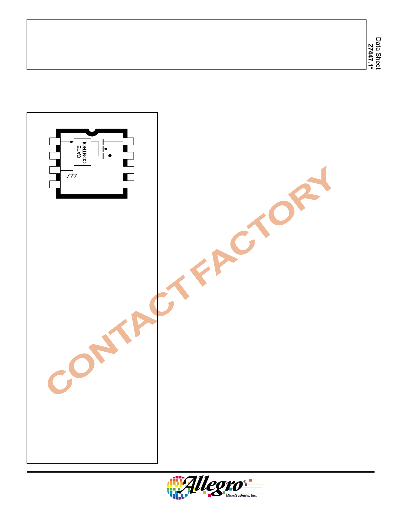
The A2525EL/M and A2535EL/M are integrated high-side power
switches, optimized for self-powered and bus-powered Universal Serial
Bus (USB) applications. Few external components are necessary to
EN 1
8 OUT satisfy USB requirements. The A2525EL/EM ENABLE inputs are
FLG 2
7 IN
active high; the A2535EL/EM are active low.
All devices are ideally suited for USB applications. Each switch
GND 3
NC 6 NC
channel supplies up to 500 mA as required by USB peripheral devices.
NC 4 NC
NC 5 NC
YDwg. PP-070A
RNote that the A2525EM (DIP) and the
OA2525EL (SOIC) are electrically identical and
Tshare a common terminal number assignment.
FACABSOLUTE MAXIMUM RATINGS
Supply Voltage, VIN ..................... 6.0 V
TOutput Voltage, VOUT .................. 6.0 V
COutput Current,
IOUT ................. Internally Limited
AENABLE Voltage Range,
VEN ......................... –0.3 V to 10 V
TFault Flag Voltage, VFLG .............. 8.0 V
NFault Flag Current, IFLG ............. 50 mA
Package Power Dissipation,
OPD ................................. See Graph
Operating Temperature Range,
CTA .......................... -40°C to +85°C
In addition, the switch’s low on-resistance permits achieving the USB
voltage-drop requirements. Fault current is limited to typically
750 mA, satisfying the UL 25 VA safety requirements, and a flag
output is available to indicate a fault condition to the local USB
controller. Momentary voltage drops that may occur on the upstream
port when the switch is enabled in bus-powered applications is elimi-
nated by a “soft start” feature.
Additional features include thermal shutdown to prevent catastrophic
switch failure from high-current loads, undervoltage lockout to ensure
that the device remains OFF unless there is a valid input voltage
present, and 3.3 V and 5 V logic-compatible enable inputs.
These switches are provided in 8-pin mini-DIP (suffix ‘M’) and
8-lead SOIC (suffix ‘L’) packages.
Features
I 2.7 V to 5.8 V Input
I Up to 500 mA Continuous Load Current per Port
I 140 mΩ Maximum ON-Resistance
I 1.25 A Maximum Short-Circuit Current Limit
I Individual Open-Drain Fault Flag Outputs
I 100 µA Typical ON-State Supply Current
I <1 µA Typical OFF-State Supply Current
I Outputs Can be Forced Higher Than Input (off-state)
I Thermal Shutdown
I 2.2 V Typical Undervoltage Lockout
I 0.6 ms Turn On (soft-start) and Fast Turn Off
Junction Temperature, TJ ....... +150°C*
Storage Temperature Range,
I A2525 (active-high) Improved Replacement for MIC2525-1
I A2535 (active-low) Improved Replacement for MIC2525-2
TS ........................... -65°C to 150°C
Applications
* Fault conditions that produce excessive
junction temperature will activate device
thermal shutdown circuitry. These conditions
can be tolerated but should be avoided.
I USB Hosts and Self-Powered Hubs
I USB Bus-Powered Hubs
I Hot Plug-In Power Supplies
I Battery-Charger Circuits
1 page 
2525 AND 2535
USB
POWER CONTROL
SWITCHES
NO-LOAD SWITCHING PERFORMANCE
VOUT
1 V/
VENABLE
200 µs/
VOUT
1 V/
VENABLE
50 µs/
VOUT
1 V/
VENABLE
www.allegromicro.com
50 µs/
5
5 Page 
8
0.280
0.240
2525 AND 2535
USB
POWER CONTROL
SWITCHES
A2525EM and A2535EM
Dimensions in Inches
(controlling dimensions)
0.014
0.008
5
0.430
MAX
0.300
BSC
1
0.070
0.045
0.210
MAX
0.400
0.355
4
0.005
MIN
0.015
MIN
0.022
0.014
0.100
BSC
0.150
0.115
Dwg. MA-001-8A in
8
7.11
6.10
Dimensions in Millimeters
(for reference only)
0.355
0.204
5
10.92
MAX
7.62
BSC
1
1.77
1.15
5.33
MAX
10.16
9.02
4
0.13
MIN
0.39
MIN
0.558
0.356
2.54
BSC
3.81
2.93
NOTES: 1. Leads 1, 4, 5, and 8 may be half leads at vendor’s option.
2. Lead thickness is measured at seating plane or below.
3. Lead spacing tolerance is non-cumulative.
4. Exact body and lead configuration at vendor’s option within limits shown.
Dwg. MA-001-8A mm
www.allegromicro.com
11
11 Page | ||
| Páginas | Total 12 Páginas | |
| PDF Descargar | [ Datasheet A2525.PDF ] | |
Hoja de datos destacado
| Número de pieza | Descripción | Fabricantes |
| A2521 | Grounded Grid Triode | GEC |
| A2525 | USB POWER CONTROL SWITCHES | Allegro MicroSystems |
| A2526 | USB DUAL POWER CONTROL SWITCHES | Allegro MicroSystems |
| Número de pieza | Descripción | Fabricantes |
| SLA6805M | High Voltage 3 phase Motor Driver IC. |
Sanken |
| SDC1742 | 12- and 14-Bit Hybrid Synchro / Resolver-to-Digital Converters. |
Analog Devices |
|
DataSheet.es es una pagina web que funciona como un repositorio de manuales o hoja de datos de muchos de los productos más populares, |
| DataSheet.es | 2020 | Privacy Policy | Contacto | Buscar |