|
|
|
PDF UCS2112 Data sheet ( Hoja de datos )
| Número de pieza | UCS2112 | |
| Descripción | USB Dual-Port Power Switch and Current Monitor | |
| Fabricantes | Microchip | |
| Logotipo | ||
Hay una vista previa y un enlace de descarga de UCS2112 (archivo pdf) en la parte inferior de esta página. Total 30 Páginas | ||
|
No Preview Available !
UCS2112
USB Dual-Port Power Switch and Current Monitor
Features
• Dual-Port Power Switches:
- 2.9V to 5.5V source voltage range
- 3.0A continuous current per VBUS port with
40 m On resistance per switch
- Independent port power switch enable pins
- DUAL fault ALERT# active drain output pins
- Constant Current or Trip mode current
limiting behaviors
- Undervoltage and overvoltage lockout
- Back-drive, back-voltage protection
- Auto-recovery fault handling with low test
current
- BOOST# logic output to increase DC-DC
converter output under large load conditions
- A_DET# open-drain outputs for device attach
detection per port
• SMBus 2.0/I2C™ Mode Features:
- Eight programmable current limits assignable
to each power switch
- Other SMBus addresses available upon
request
- Block read and block write
• Self-contained current monitoring (no external
sense resistor required)
• Fully programmable per-port charge rationing and
behaviors
• Per-port BC1.2 VBUS Discharge Function
• Wide Operating Temperature Range:
- -40°C to +105°C
• UL recognized and EN/IEC 60950-1 (CB) certified.
Description
The UCS2112 is a dual USB port power switch
configuration which can provide 3.0A continuous
current (3.4A maximum) per VBUS port with precision
overcurrent limiting (OCL), port power switch enables,
auto-recovery fault handling, undervoltage and
overvoltage lockout, back-drive protection and
back-voltage protection, and dynamic thermal
management.
The UCS2112 is well suited for both stand-alone and
applications having SMBus/I2C communications.
For applications with SMBus, the UCS2112 provides
per-port current monitoring and eight programmable
current limits per switch, ranging from 0.53A to 3.0A
continuous current (3.4A maximum). Per-port charge
rationing is also provided ranging from 3.8 mAh to
246.3 Ah.
In Stand-alone mode, the UCS2112 provides eight
current limits for both switches, ranging from
0.53A + 0.53A to 3A + 3A total continuous current
(see Table 1-1).
Both power switches include an independent VBUS dis-
charge function and constant current mode current lim-
iting for BC1.2 applications.
The UCS2112 is available in a 4x4 mm 20-pin QFN
package.
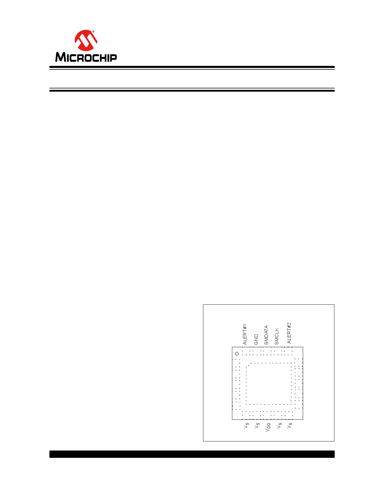
Package Type
UCS2112
4x4 QFN*
20 19 18 17 16
PWR_EN1 1
15 PWR_EN2
A_DET#1 2
BOOST# 3
EP 14 A_DET#2
21 13 COMM_ILIM
VBUS1 4
12 VBUS2
VBUS1 5
11 VBUS2
6 7 8 9 10
* Includes Exposed Thermal Pad (EP); see Table 3-1.
2015 Microchip Technology Inc.
DS20005424B-page 1
1 page 
UCS2112
TABLE 1-2: ELECTRICAL SPECIFICATIONS (CONTINUED)
Electrical Characteristics: Unless otherwise specified, VDD = 4.5V to 5.5V, VS = 2.9V to 5.5V,
VPULLUP = 3V to 5.5V, TA = -40°C to 105°C. All typical values at VDD = VS = 5V, TA = 27°C.
Characteristic
Symbol
Min. Typ. Max. Unit
Conditions
Port Power Switch
Port Power Switch - DC Parameter
Overvoltage Lockout
VS Low Threshold
VS Low Hysteresis
On Resistance
VS Leakage Current
VS_OV
— 6 — V Note 2
VS_UVLO
— 2.5
—
V Note 2
VS_UVLO_HYST
—
100
—
mV Note 2
RON_PSW
— 40
— m 4.75V < VS < 5.25V
ILEAK_VS — — 5 µA Sleep state into VS pin on one
channel (Note 1)
Back-voltage Protection
Threshold
Back-drive Current
VBV_TH
IBD_1
— 150
—0
—
3
mV VBUS > VS
VS > VS_UVLO
µA VDD < VDD_TH,
Leakage current from VBUS pins
to the VDD and the VS pins
(Note 1)
IBD_2
— 0 2 µA VDD > VDD_TH,
Leakage current from VBUS pins
to the VDD (in Detect State) or
the VS pins (in Active State)
(Note 1)
Selectable Current Limits
ILIM1
— 530
—
mA ILIM Resistor = 0 or 47 k
(530 mA setting)
ILIM2
— 960
—
mA ILIM Resistor = 10 k or 56 k
(960 mA setting) (Note 4)
ILIM3
— 1070 —
mA ILIM Resistor = 12 k or 68 k
(1070 mA setting) (Note 4)
ILIM4
— 1280 —
mA ILIM Resistor = 15 k or 82 k
(1280 mA setting) (Note 4)
ILIM5
— 1600 —
mA ILIM Resistor = 18 k or 100 k
(1600 mA setting) (Note 4)
ILIM6
— 2130 —
mA ILIM Resistor = 22 k or 120 k
(2130 mA setting) (Note 4)
ILIM7
— 2670 —
mA ILIM Resistor = 27 k or 150 k
(2670 mA setting) (Note 4)
ILIM8
3000 3200 3400
mA ILIM Resistor = 33 k or VDD
(3200 mA setting)
Pin Wake Time
SMBus Wake Time
Idle Sleep Time
Thermal Regulation Limit
tPIN_WAKE
tSMB_WAKE
tIDLE_SLEEP
TREG
—3
—4
— 200
— 110
—
—
—
—
ms
ms
ms
°C Die Temperature at which
current limit will be reduced
Thermal Regulation
Hysteresis
TREG_HYST — 10 — °C Hysteresis for tREG functionality.
Temperature must drop by this
value before ILIM value restored
to normal operation
Note 1:
2:
3:
4:
This parameter is characterized, not 100% tested.
This parameter is ensured by design and not 100% tested.
The current measurement full scale range maximum value is 3.4A. However, the UCS2112 cannot report values above
ILIM (if IBUS_R2MIN ILIM) or above IBUS_R2MIN (if IBUS_R2MIN > ILIM and ILIM 1.6A).
This parameter is characterized, not 100% production tested.
2015 Microchip Technology Inc.
DS20005424B-page 5
5 Page 
UCS2112
2.0 TYPICAL PERFORMANCE CURVES
Note:
The graphs and tables provided following this note are a statistical summary based on a limited number of
samples and are provided for informational purposes only. The performance characteristics listed herein
are not tested or guaranteed. In some graphs or tables, the data presented may be outside the specified
operating range (e.g., outside specified power supply range) and therefore outside the warranted range.
Note: Unless otherwise indicated, VDD = VS = 5V, TA = +27°C.
66
VS = VDD = 5V
5 5ILIM = 3A min (3.4A max), short applied at 2 ms
ALERT#
4 IBUS
4
33
22
1
0 VBUS
1
0
-1
0
FIGURE 2-1:
Power-Up.
5
Time (ms)
-1
10
Short Applied After
6
5
4
3
2
1
0
-1
0
VBUS
100
FIGURE 2-4:
200 300 400 500
Time (ms)
VBUS Discharge Behavior.
6
5 VDD
ALERT#
4
6
5
4
33
22
1
0 IBUS
1
0
-1
0
-1
100 200 300 400 500
Time (ms)
FIGURE 2-2:
Power-Up Into a Short.
45
40
35
30
25
20
15
10
5
0
-40
-15
10 35 60
Temperature (°C)
85
FIGURE 2-5:
Power Switch On
Resistance vs. Temperature.
110
6
5
VBUS
4
3
2
1
0
-1 IBUS
-2
0
FIGURE 2-3:
Response.
VS = VDD = 5V
ILIM = 2.13A (typical), short applied at 10 µs
28
24
20
16
12
8
4
0
-4
20 40
Time (µs)
Internal Power Switch Short
2015 Microchip Technology Inc.
DS20005424B-page 11
11 Page | ||
| Páginas | Total 30 Páginas | |
| PDF Descargar | [ Datasheet UCS2112.PDF ] | |
Hoja de datos destacado
| Número de pieza | Descripción | Fabricantes |
| UCS2112 | USB Dual-Port Power Switch and Current Monitor | Microchip |
| Número de pieza | Descripción | Fabricantes |
| SLA6805M | High Voltage 3 phase Motor Driver IC. |
Sanken |
| SDC1742 | 12- and 14-Bit Hybrid Synchro / Resolver-to-Digital Converters. |
Analog Devices |
|
DataSheet.es es una pagina web que funciona como un repositorio de manuales o hoja de datos de muchos de los productos más populares, |
| DataSheet.es | 2020 | Privacy Policy | Contacto | Buscar |