|
|
|
PDF UT54ACTQ16244 Data sheet ( Hoja de datos )
| Número de pieza | UT54ACTQ16244 | |
| Descripción | RadHard CMOS 16-bit Buffer/Line Driver | |
| Fabricantes | Aeroflex Circuit Technology | |
| Logotipo | ||
Hay una vista previa y un enlace de descarga de UT54ACTQ16244 (archivo pdf) en la parte inferior de esta página. Total 12 Páginas | ||
|
No Preview Available !
Standard Products
UT54ACTQ16244
RadHard CMOS 16-bit Buffer/Line Driver, TTL Inputs, and
Three-State Outputs
Datasheet
May 16, 2012
www.aeroflex.com/radhard
FEATURES
16 non-inverting buffers with three-state outputs
Guaranteed simultaneously switching noise level and dy-
namic threshold performance
Separate control logic for each byte and nibble
0.6m Commercial RadHardTM CMOS
- Total dose: 100K rad(Si)
- Single Event Latchup immune
High speed, low power consumption
Output source/sink 24mA
Standard Microcircuit Drawing 5962-06243
- QML compliant part
Package:
- 48-lead flatpack, 25 mil pitch (.390 x .640)
DESCRIPTION
The 16-bit wide UT54ACTQ16244 buffer/line driver is built
using Aeroflex’s Commercial RadHardTM epitaxial CMOS
technology and is ideal for space applications. This high speed,
low power UT54ACTQ16244 buffer/line driver is designed to
improve the performance and density of three-state memory
address drivers, clock drivers, and bus-oriented receivers and
transmitters. The UT54ACTQ16244 can be used as four 4-bit
(nibble) buffers, two 8-bit (byte) buffers, or one 16-bit buffer.
The device provides true outputs and symmetrical OE (active-
low) output-enable inputs. The device is nibble controlled with
each nibble functioning identically, but independent of each oth-
er. The control pins can be shorted together to obtain full 16-bit
operation.
PIN DESCRIPTION
Pin Names
Description
OEn
I0-I15
Output Enable Input (Active Low)
Inputs
O0-O15 Outputs
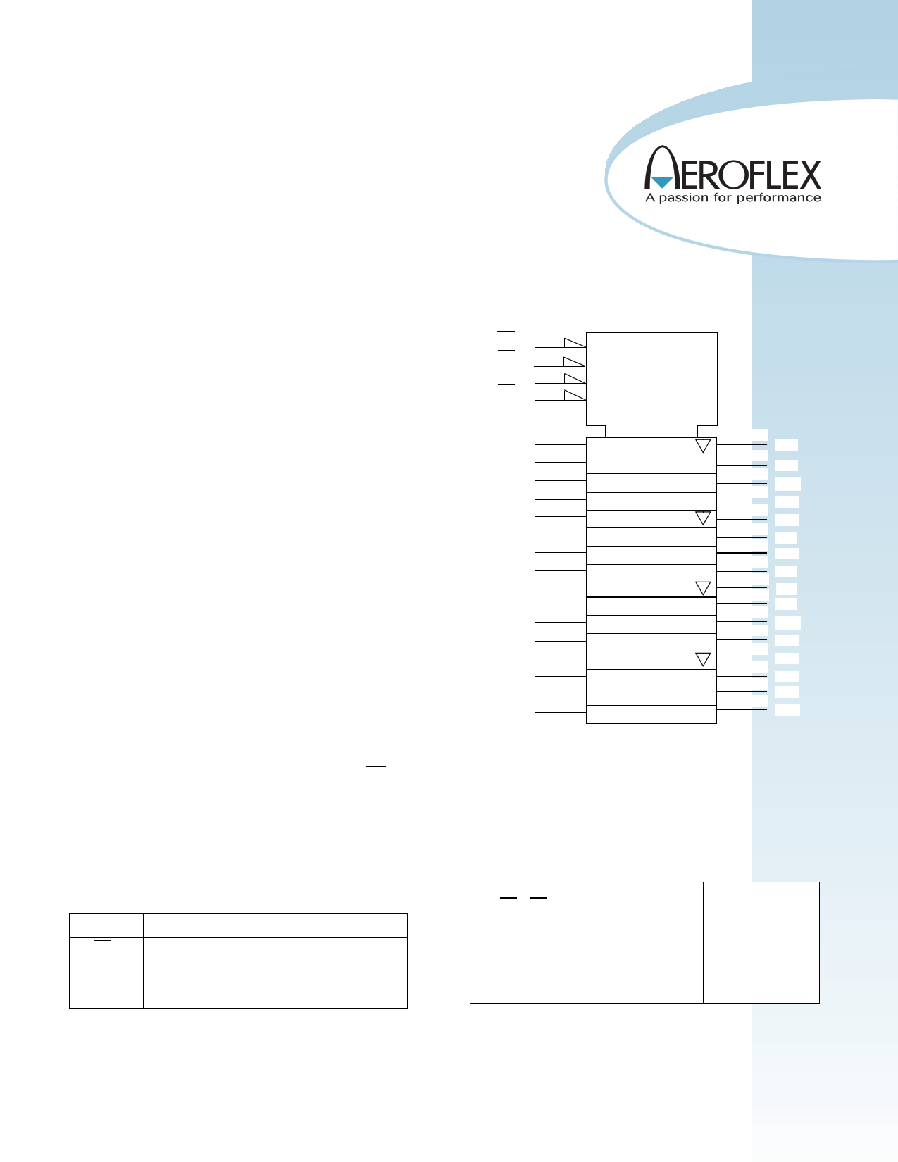
LOGIC SYMBOL
OE1 (1)
OE2 (48)
OE3 (25)
OE4 (24)
EN1
EN2
EN3
EN4
(47)
I0
(46)
I1
(44)
I2
(43)
I3
(41)
I4
(40)
I5
(38)
I6
(37)
I7
(36)
I8
(35)
I9
(33)
I10
(32)
I11
(30)
I12
(29)
I13
(27)
I14
(26)
I15
11 1
12
13
14
(2)
O0
(3)
O1
(5)
O2
(6)
O3
(8)
O4
(9)
(11) O5
O6
(12)
(13) O7
(14) O8
O9
(16)
O10
(17)
O11
(19)
O12
(20)
(22)
O13
O14
(23)
O15
FUNCTION TABLE
ENABLE
OE1, OE2,
OE3, OE4
Inputs
I0-I3, I4-I7,
I8-I11, I12-I15
LL
LH
HX
Outputs
O0-O3, O4-07,
O8-O11, O12-O15
L
H
Z
1
1 page 
DC ELECTRICAL CHARACTERISTICS 1
(-55C < TC < +125C)
SYMBOL
PARAMETER
VIL Low level input voltage2
VIH High level input voltage2
IIN Input leakage current3
IOZ Three-state output leakage current3
IOS Short-circuit output current 4, 5
VOL1 Low-level output voltage3, 6
VOL2 Low-level output voltage3, 6, 7
VOH1 High-level output voltage3, 6
VOH2 High-level output voltage3, 6, 7
VIC+ Positive input clamp voltage
VIC- Negative input clamp voltage
CONDITION
MIN
VDD from 4.5 to 5.5V
VDD from 4.5 to 5.5V
2.0
VDD from 4.5V to 5.5V
VIN = VDD or VSS
-1
VDD from 4.5V to 5.5V
VIN = VDD or VSS
-10
VO = VDD or VSS
VDD from 4.5V to 5.5V
-600
IOL= 24mA
-55C, 25C
IOL= 24mA
+125C
IOL= 100A
-55C, 25C,
VDD = 4.5V to 5.5V +125C
VIN = 0.8V to 2.0V
IOL= 50mA
-55C, 25C
VIN = 2.0V or 0.8V
VDD = 5.5V
VIN = 0.8V to 2.0V
+125C
IOH= -24mA
-55C, 25C
IOH= -24mA
+125C
IOH= -100A
-55C, 25C,
VDD = 4.5V to 5.5V +125C
VIN = 0.8V to 2.0V
VDD - 0.64
VDD - 0.8
VDD - 0.2
IOH= -50mA
-55C, 25C
VIN = 2.0V or 0.8V
VDD = 5.5V
+125C
VIN = 0.8V to 2.0V
VDD - 1.1
VDD - 1.3
For input under test, IIN = 18mA
VDD = 0.0V
0.4
For input under test, IIN =-18mA
VDD = open
-1.5
MAX
0.8
1
10
600
0.36
0.5
0.2
0.8
1.0
1.5
-0.4
UNIT
V
V
A
A
mA
V
V
V
V
V
V
5
5 Page 
UT54ACTQ16244
UT54 **** ***** * * *
Lead Finish: (NOTES 1 & 2)
(A) = Hot solder dip
(C) = Gold
(X) = Factory option (gold or solder)
Screening: (NOTES 3 & 4)
(C) = Mil Temp
(P) = Prototype
Package Type:
(U) = 48-lead BB FP
Part Number:
(16244) = 16-bit Buffer Line Driver
I/O Type:
(ACTQ)= TTL compatible I/O Level with Quiet Outputs
Aeroflex Core Part Number
Notes:
1. Lead finish (A, C, or X) must be specified.
2. If an “X” is specified when ordering, then the part marking will match the lead finish and will be either “A” (solder) or “C” (gold).
3. Prototype flow per Aeroflex Manufacturing Flows Document. Tested at 25C only. Lead finish is Gold "C" only. Radiation neither tested nor guaranteed.
4. Military Temperature Range flow per Aeroflex Manufacturing Flows Document. Devices are tested at -55C, room temp, and 125C. Radiation neither tested nor
guaranteed.
11
11 Page | ||
| Páginas | Total 12 Páginas | |
| PDF Descargar | [ Datasheet UT54ACTQ16244.PDF ] | |
Hoja de datos destacado
| Número de pieza | Descripción | Fabricantes |
| UT54ACTQ16244 | RadHard CMOS 16-bit Buffer/Line Driver | Aeroflex Circuit Technology |
| UT54ACTQ16245 | RadHard CMOS 16-bit Bidirectional Transceiver | Aeroflex Circuit Technology |
| Número de pieza | Descripción | Fabricantes |
| SLA6805M | High Voltage 3 phase Motor Driver IC. |
Sanken |
| SDC1742 | 12- and 14-Bit Hybrid Synchro / Resolver-to-Digital Converters. |
Analog Devices |
|
DataSheet.es es una pagina web que funciona como un repositorio de manuales o hoja de datos de muchos de los productos más populares, |
| DataSheet.es | 2020 | Privacy Policy | Contacto | Buscar |