|
|
|
PDF PT7M7438 Data sheet ( Hoja de datos )
| Número de pieza | PT7M7438 | |
| Descripción | uP Supervisory Circuit | |
| Fabricantes | Pericom Technology | |
| Logotipo | ||
Hay una vista previa y un enlace de descarga de PT7M7438 (archivo pdf) en la parte inferior de esta página. Total 6 Páginas | ||
|
No Preview Available !
GND 3
GND 3
2 BATT
2 BATT
PT7M7436/37/38
||||||||||||||||||||||||||||||||||||||||||||||||||||||||||||||||||||||||||||||||||||||||||||S||||O|||||T|||||2|||3||||-||5||||||||||| |||||||||||||||||||||||||||||||||||||||||||||||||||||||||||||||||||||||||||||||||||||||||||||||||||||||||||||||||||||||||||||||||||||||||||||||||||||||||||||||||||||||||||||||||||||||||||||||||||||| ||||||||||||||||||||||||||||||||||||||||||||||||||
PT7M7430xx
P Supervisory CircuitPT7M7431xx
PT7M7432xx
Features
1 GND LBOL D5 escription
1 GND LBOL 5
User-Adjustable Low/High Thresholds with The PT7M7436/37/38 are dual-level battery monitors
585mV/615mV Internal Reference
Low Current (1.5μA typ)
2 NC
with internal hysteresis. These devices are offered with
2 NC
dual low-battery output indicators which can be used to
Dual Low-Battery Outputs
3 LBOH BATT i4ndicate three battery3 coLnBdOiHtionBsA:TgToo4d (operate system
Push-Pull active low, Open-Drain active low and in normal mode), weak (operate system in low-power
Open-Drain active high output options
mode), or empty (disable the system).
90ms Minimum LBOA/LBOL TimPeTo7uMt 7P4e3r3iod
PT7M7434
Immune to Short Battery Voltage Transients
-40°C to + 85°C Operating Temp1eraHtTuHrIeN RaVnCgCe 5
AppPlTi7cMat7i4o35ns
1 MHoTnHiItNorinVgCClit5hiumion
PT7M7479H
PT7M7479L
(L1i+) HTcHells VoDrD m5ulticell
2 GND
alkaline/ NiCd/ NiMH power supplies.
2 GND
2 GND
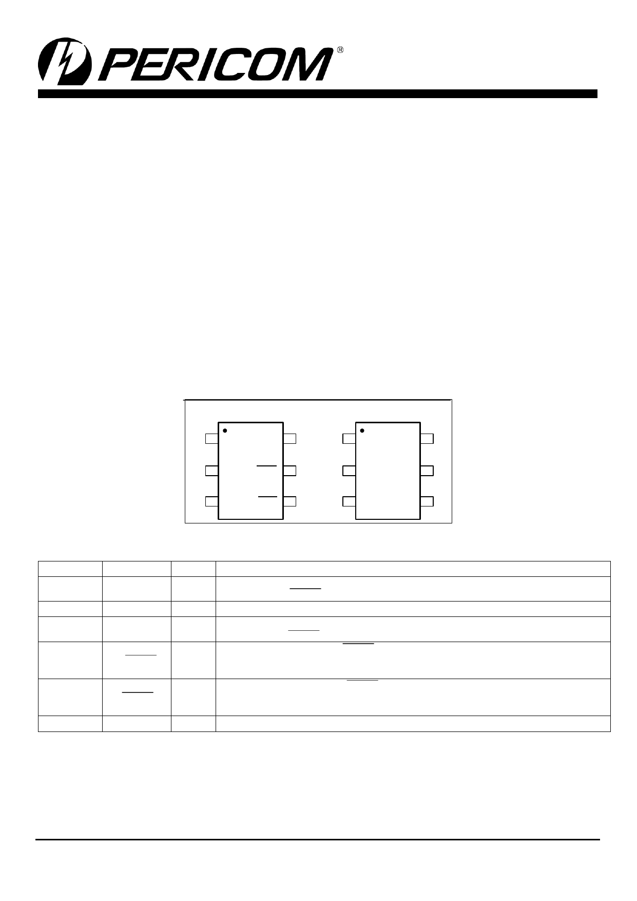
Pin Configuration
3 LTHIN LBO 4
SOT23-6
PT7M7436
PT7M7437
1 HTHIN VCC 6
3 LTHIN LBO 4
PT7M7438
1 HTHIN VCC 6
3 LTH
RST
(/RST) 4
PT7M3806M
PT7M3806E
1 RSTSENSE HSENSE 6
2 GND LBOH 5
2 GND LBOH 5
2 GND
LSENSE 5
3 LTHIN LBOL 4
3 LTHIN LBOL 4
3 RESET
VCC 4
Pin Description
Pin Name
1 HTHIN
2 GND
3 LTHIN
4 LBOL
/LBOL
5 LBOH
/LBOH
6 VCC
Type
I
P
I
O
O
P
Description
HTH Threshold Monitor Input. A resistor-divider network sets the high threshold
associated with LBOH/LBOH.
Ground
LTH Threshold Monitor Input. A resistor-divider network sets the low threshold
associated with LBOL/LBOL.
Low-Battery Output Low. LBOL/LBOL is asserted when LTHIN drops below VLTHIN-.
It remains asserted for at least 90ms after LTHIN rises above VLTHIN+. Push-pull output
for PT7M7436, open-drain output for PT7M7437/38.
Low-Battery Output High. LBOH/LBOH is asserted when HTHIN drops below
VHTHIN. It remains asserted for at least 90ms after HTHIN rises above VHTHIN+. Push-pull
output for PT7M7436, open-drain output for PT7M7437/38.
Supply Voltage. Device power supply.
12-07-0002
PT0212-6
07/05/12
1
1 page 
PT7M7436/37/38
P Supervisory Circuit
||||||||||||||||||||||||||||||||||||||||||||||||||||||||||||||||||||||||||||||||||||||||||||||||||||||||||||||||||||||||||||| |||||||||||||||||||||||||||||||||||||||||||||||||||||||||||||||||||||||||||||||||||||||||||||||||||||||||||||||||||||||||||||||||||||||||||||||||||||||||||||||||||||||| ||||||||||||||||||||||||||||||||||||||||||||||||||||||||||||||||||||||||||||||||
Application Information
Resistor-Value Selection (Programming the Adjustable
Thresholds)
VREF = VLTHIN- = VHTHIN- = 585mV
VTRIPLOW = VLTH- = VREF (
R1 + R2 + R3
R2 + R3
)
VTRIPHIGH = VHTL- = VREF (
R1 + R2 + R3
R3
)
RTOTAL = R1 + R2 + R3
Use the following steps to determine values for R1, R2, and
R3 of Functional Block Diagram.
1) Choose a value for RTOTAL, the sum of R1, R2, and R3.
Because the PT7M7436~PT7M7438 have very high input
impedances, RTOTAL can be up to 5MΩ.
2) Calculate R3 based on RTOTAL and the desired upper trip
point:
×R3 =
VREF RTOTAL
VTRIPHIGH
×=
585mV RTOTAL
VTRIPHIGH
3) Calculate R2 based on RTOTAL, R3, and the desired lower
trip point:
R2
=
585mV ×RTOTAL
VTRPLOW
- R3
4) Calculate R1 based on RTOTAL, R3, and R2:
R1 = RTOTAL – R2 – R3
VHTH+ = VHTH- ×1.05, VLTH+ = VLTH- ×1.05
Mechanical Information
TAE (SOT23-6)
Note:
1) Controlling dimensions in millimeters.
12-07-0002
5
PKG. DIMENSIONS(MM)
SYMBOL Min
Max
A 0.70 0.90
A1 0.00 0.10
A2 0.70 0.80
b 0.35 0.50
c 0.08 0.20
D 2.82 3.02
E 1.60 1.70
E1 2.65 2.95
e 0.95 BSC
e1 1.90 BSC
L 0.30 0.60
θ 0° 8°
PT0212-6
07/05/12
5 Page | ||
| Páginas | Total 6 Páginas | |
| PDF Descargar | [ Datasheet PT7M7438.PDF ] | |
Hoja de datos destacado
| Número de pieza | Descripción | Fabricantes |
| PT7M7433 | uP Supervisory Circuit | Pericom Technology |
| PT7M7434 | uP Supervisory Circuit | Pericom Technology |
| PT7M7435 | uP Supervisory Circuit | Pericom Technology |
| PT7M7436 | uP Supervisory Circuit | Pericom Technology |
| Número de pieza | Descripción | Fabricantes |
| SLA6805M | High Voltage 3 phase Motor Driver IC. |
Sanken |
| SDC1742 | 12- and 14-Bit Hybrid Synchro / Resolver-to-Digital Converters. |
Analog Devices |
|
DataSheet.es es una pagina web que funciona como un repositorio de manuales o hoja de datos de muchos de los productos más populares, |
| DataSheet.es | 2020 | Privacy Policy | Contacto | Buscar |